Mitsubishi Lancer (4A9 engine). Manual - part 307
COMPRESSOR ASSEMBLY
HEATER, AIR CONDITIONER AND VENTILATION
55A-109
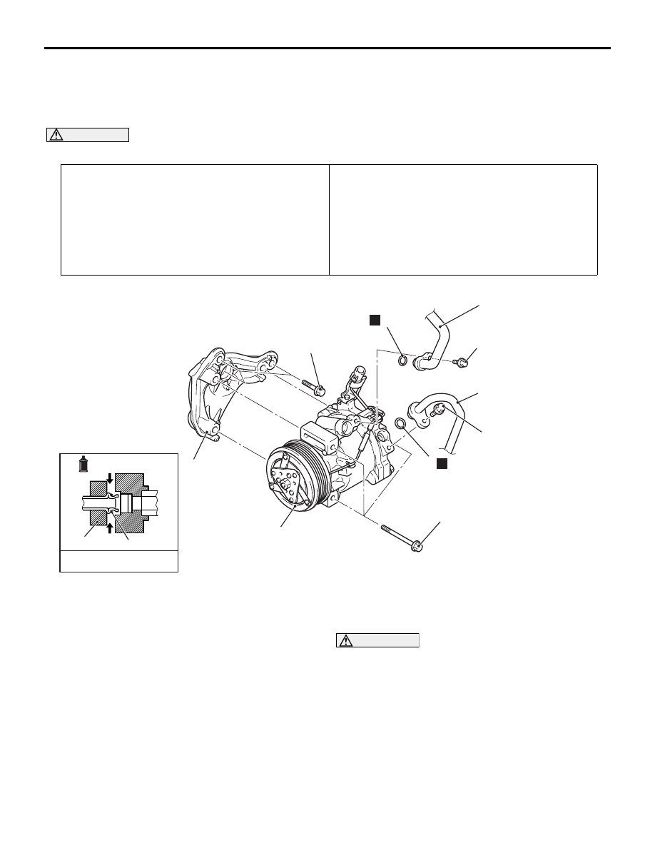
COMPRESSOR ASSEMBLY
REMOVAL AND INSTALLATION <1600 (M/
T)>
M1552004403580
CAUTION
•
Pre-removal operation
• Discharging refrigerant (Refer to )
• Engine room under cover front A and B, Engine room side
cover removal (Refer to GROUP 51, Under Cover ).
• Drive belt removal (Refer to GROUP 11A Crankshaft Pul-
ley )
Post-installation Operation
• Drive belt installation (Refer to GROUP 11A Crankshaft
Pulley )
• Drive belt tension check and adjustment (Refer to
GROUP 11A
− Drive Belt Tension Check ). <Petrol
engine>
• Charging refrigerant (Refer to )
• Engine room under cover front A and B, Engine room side
cover installation (Refer to GROUP 51, Under Cover ).
ACB01639
1, 2
3
5
3
1
2
4
AB
3
N
N
10 ± 2 N·m
10 ± 2 N·m
23 ± 6 N·m
A/C compressor oil:
SUN PAG 56 or S10X
-Pipe coupling
23 ± 6 N·m
Removal steps
<<
A
>>
1.
Discharge flexible hose connection
<<
A
>>
2.
Suction flexible hose connection
3.
O-ring
<<
B
>>
>>
A
<<
4.
A/C compressor and clutch
assembly
5.
A/C compressor bracket
When removing the compressor, be careful not to subject the pulley and the clutch to impact.
NOTE: The service points which are not described
are the same as before.
REMOVAL SERVICE POINTS
<<A>> DISCHARGE FLEXIBLE HOSE/SUCTION
FLEXIBLE HOSE DISCONNECTION
CAUTION
Use the plug which is not breathable because A/
C compressor oil or receiver have high hygro-
scopicity.
Plug the hose nipple removed to prevent the entry of
dust and dirt.
<<B>> A/C COMPRESSOR AND CLUTCH
ASSEMBLY REMOVAL
Be careful not to spill the A/C compressor oil and
remove the A/C compressor.