Mitsubishi Lancer (4A9 engine). Manual - part 255


  Index      Mitsubishi     Mitsubishi Lancer (4A9 engine) 12GS41 & 44S - service repair manual


Search            


Content   ..  253  254  255  256   ..


Mitsubishi Lancer (4A9 engine). Manual - part 255


TROUBLESHOOTING

CONTROLLER AREA NETWORK (CAN)

54C-44

<CAN_H>

OK: 1 k

 or more

(3) Measure the resistance between C-03 joint 

connector (CAN2) terminal No.22 and body 
earth. <CAN_L>

OK: 1 k

 or more

Q: Is the check result normal?

YES : 

Check the ETACS-ECU connector, and 

repair if necessary. If the ETACS-ECU 
connector is in good condition, replace the 
ETACS-ECU.

NO : 

Repair the wiring harness between C-301 
ETACS-ECU connector and C-03 joint 
connector (CAN2).

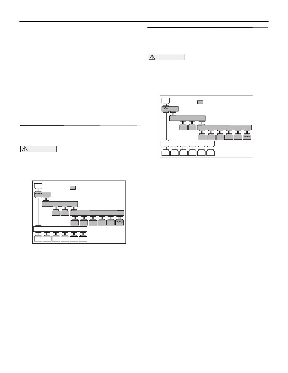
STEP 13. M.U.T.-III CAN bus diagnostics 
(checking the headlamp automatic levelling-ECU 
for internal short to earth)

CAUTION

Strictly observe the specified wiring harness 
repair procedure. For details refer to .
Disconnect C-14 headlamp automatic levelling-ECU 
connector, and diagnose the CAN bus line.

ACB01921AB

M.U.T.

JC

JC

SAS

KOS/
WCM

SRS

A/C

AUDIO

METER

AT/

CVT

EPS

ENGINE

ETACS

ABS/

ASC

MMCS

: Red section on screen

AS&G

Levelling

Cor ner

JC

OK: The display of the M.U.T.-III is as shown 
in the figure.

Q: Does M.U.T.-III screen correspond to the 

illustration?
YES : 

Repair the wiring harness between C-14 

headlamp automatic levelling-ECU 
connector and C-124 joint connector 
(CAN3).

NO : 

Check the C-14 headlamp automatic 
levelling-ECU connector, and repair if 
necessary. If the C-14 headlamp automatic 
levelling-ECU connector is in good 
condition, replace the C-14 headlamp 
automatic levelling-ECU.

STEP 14. M.U.T.-III CAN bus diagnostics 
(checking the ABS-ECU <vehicles without ASC> 
or ASC-ECU <vehicles with ASC> for internal 
short to earth)

CAUTION

Strictly observe the specified wiring harness 
repair procedure. For details refer to .
Disconnect A-04 ABS-ECU connector <vehicles 
without ASC> or A-58 ASC-ECU connector <vehi-
cles with ASC>, and diagnose the CAN bus line.

ACB01921AB

M.U.T.

JC

JC

SAS

KOS/
WCM

SRS

A/C

AUDIO

METER

AT/

CVT

EPS

ENGINE

ETACS

ABS/

ASC

MMCS

: Red section on screen

AS&G

Levelling

Cor ner

JC

OK: The display of the M.U.T.-III is as shown 
in the figure.

Q: Does M.U.T.-III screen correspond to the 

illustration?
YES : 

Repair the wiring harness between A-04 

ABS-ECU connector <vehicles without 
ASC> or A-58 ASC-ECU connector 
<vehicles with ASC> and C-124 joint 
connector (CAN3).

NO : 

Check the ABS-ECU connector <vehicles 
without ASC> or ASC-ECU connector 
<vehicles with ASC>, and repair if 
necessary. If the ABS-ECU connector 
<vehicles without ASC> or ASC-ECU 
connector <vehicles with ASC> is in good 
condition, replace the ABS-ECU <vehicles 
without ASC> or ASC-ECU <vehicles with 
ASC>.

TROUBLESHOOTING

CONTROLLER AREA NETWORK (CAN)

54C-45

STEP 15. M.U.T.-III CAN bus diagnostics 
(checking the A/T-ECU <A/T> or CVT-ECU <CVT> 
for internal short to earth)

CAUTION

Strictly observe the specified wiring harness 
repair procedure. For details refer to .
Disconnect C-32 A/T-ECU connector <A/T> or C-35 
CVT-ECU connector <CVT>, and diagnose the CAN 
bus line.

ACB01921AB

M.U.T.

JC

JC

SAS

KOS/
WCM

SRS

A/C

AUDIO

METER

AT/

CVT

EPS

ENGINE

ETACS

ABS/

ASC

MMCS

: Red section on screen

AS&G

Levelling

Cor ner

JC

OK: The display of the M.U.T.-III is as shown 
in the figure.

Q: Does M.U.T.-III screen correspond to the 

illustration?
YES : 

Repair the wiring harness between C-32 A/

T-ECU connector <A/T> or C-35 CVT-ECU 
connector <CVT> and C-124 joint connector 
(CAN3).

NO : 

Check the A/T-ECU connector <A/T> or 
CVT-ECU connector <CVT>, and repair if 
necessary. If the A/T-ECU connector <A/T> 
or CVT-ECU connector <CVT> is in good 
condition, replace the A/T-ECU connector 
<A/T> or CVT-ECU connector <CVT>.

STEP 16. M.U.T.-III CAN bus diagnostics 
(checking the electric power steering-ECU for 
internal short to earth)

CAUTION

Strictly observe the specified wiring harness 
repair procedure. For details refer to .
Disconnect C-114 electric power steering-ECU con-
nector, and diagnose the CAN bus line.

ACB01921AB

M.U.T.

JC

JC

SAS

KOS/
WCM

SRS

A/C

AUDIO

METER

AT/

CVT

EPS

ENGINE

ETACS

ABS/

ASC

MMCS

: Red section on screen

AS&G

Levelling

Cor ner

JC

OK: The display of the M.U.T.-III is as shown 
in the figure.

Q: Does M.U.T.-III screen correspond to the 

illustration?
YES : 

Repair the wiring harness between C-114 

electric power steering-ECU connector and 
C-124 joint connector (CAN3).

NO : 

Check the electric power steering-ECU 
connector, and repair if necessary. If the 
electric power steering-ECU connector is in 
good condition, replace the electric power 
steering-ECU.

TROUBLESHOOTING

CONTROLLER AREA NETWORK (CAN)

54C-46

STEP 17. M.U.T.-III CAN bus diagnostics 
(checking the AS&G-ECU for internal short to 
earth)

CAUTION

Strictly observe the specified wiring harness 
repair procedure. For details refer to .
Disconnect C-64 AS&G-ECU connector, and diag-
nose the CAN bus line.

ACB01921AB

M.U.T.

JC

JC

SAS

KOS/
WCM

SRS

A/C

AUDIO

METER

AT/

CVT

EPS

ENGINE

ETACS

ABS/

ASC

MMCS

: Red section on screen

AS&G

Levelling

Cor ner

JC

OK: The display of the M.U.T.-III is as shown 
in the figure.

Q: Does M.U.T.-III screen correspond to the 

illustration?
YES : 

Repair the wiring harness between C-64 

AS&G-ECU connector and C-124 joint 
connector (CAN3).

NO : 

Check the AS&G-ECU connector, and 
repair if necessary. If the C-64 AS&G-ECU 
connector is in good condition, replace the 
AS&G-ECU.

STEP 18. M.U.T.-III CAN bus diagnostics 
(checking the engine-ECU for internal short to 
earth)

CAUTION

Strictly observe the specified wiring harness 
repair procedure. For details refer to .
Disconnect B-09 <Petrol> or B-40 <Diesel> engine-
ECU connector, and diagnose the CAN bus line.

ACB01921AB

M.U.T.

JC

JC

SAS

KOS/
WCM

SRS

A/C

AUDIO

METER

AT/

CVT

EPS

ENGINE

ETACS

ABS/

ASC

MMCS

: Red section on screen

AS&G

Levelling

Cor ner

JC

OK: The display of the M.U.T.-III is as shown 
in the figure.

Q: Does M.U.T.-III screen correspond to the 

illustration?
YES : 

Repair the wiring harness between B-09 

<Petrol> or B-40 <Diesel> engine-ECU 
connector and C-124 joint connector 
(CAN3).

NO  : 

Check the engine-ECU connector, and 
repair if necessary. If the engine-ECU 
connector is in good condition, replace the 
engine-ECU.

TROUBLESHOOTING

CONTROLLER AREA NETWORK (CAN)

54C-47

Diagnosis Item 5: Diagnose shorts in the power supply to CAN-C bus line

CAUTION

When servicing a CAN bus line, earth yourself by touching a metal object such as an unpainted water 
pipe. If you fail to do, a component connected to the CAN bus line may be broken.


Content   ..  253  254  255  256   ..