Mitsubishi Lancer (4A9 engine). Manual - part 225
ETACS
CHASSIS ELECTRICAL
54A-562
Inspection Procedure 6: The front door switch (passenger’s side) signal is not received.
CAUTION
Before replacing the ECU, ensure that the power supply circuit, the earth circuit and the communica-
tion circuit are normal.
COMMENTS ON TROUBLE SYMPTOM
If there is an error to the front door switch (passen-
ger’s side) input signal, the door switch (passenger’s
side) signal is no longer output to the communication
line.
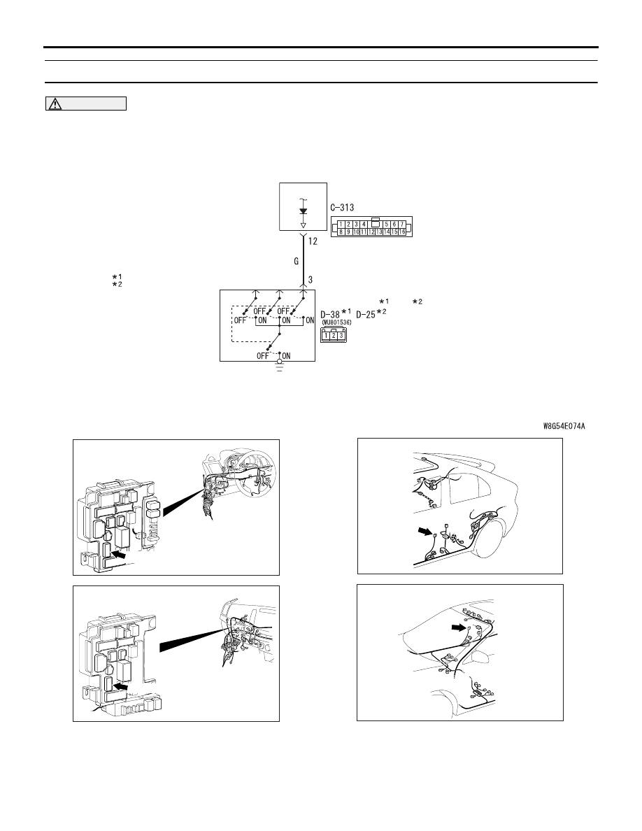
ETACS-
ECU
Front Door Switch (Passenger's Side) Input Circuit
FRONT DOOR
SWITCH (RH) (LH)
Wire colour code
B : Black LG : Light green G : Green L : Blue W : White Y : Yellow SB : Sky blue
BR : Brown O : Orange GR : Grey R : Red P : Pink V : Violet PU : Purple SI : Silver
NOTE
: LHD
: RHD
AC701240
AU
Connector: C-313 <LHD>
ETACS-ECU
C-313 (BR)
AC701241
BA
Connector: C-313 <RHD>
ETACS-ECU
C-313 (BR)
AC801769AI
Connector: D-25
AC612722
BO
Connector: D-38