Mitsubishi Lancer (4A9 engine). Manual - part 224


  Index      Mitsubishi     Mitsubishi Lancer (4A9 engine) 12GS41 & 44S - service repair manual


Search            


Content   ..  222  223  224  225   ..


Mitsubishi Lancer (4A9 engine). Manual - part 224


ETACS

CHASSIS ELECTRICAL

54A-558

Inspection Procedure 4: The front door lock actuator signal is not received. <RH drive vehicles>

CAUTION

Before replacing the ECU, ensure that the power supply circuit, the earth circuit and the communica-
tion circuit are normal.

COMMENTS ON TROUBLE SYMPTOM
The front door lock actuator (RH) input signal is used 
for the operation judgement of the functions below. If 
the signal is abnormal, these functions will not work 
normally.

• Central door locking

• KOS

• Keyless entry system

• Room lamp

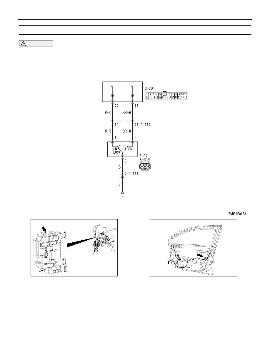
Door Look Actuator Signal Input Circuit

ETACS-ECU

FRONT DOOR 
LOCK ACTUATOR 
(RH)

Wire colour code 
B : Black     LG : Light green     G : Green     L : Blue     W : White     Y : Yellow     SB : Sky blue 
BR : Brown     O : Orange     GR : Grey     R : Red     P : Pink     V : Violet     PU : Purple     SI : Silver

AC701241

BB

Connector: C-301 <RHD>

ETACS-ECU

AC612735

Connector:E-07 <RHD>

AE

E-07 (B)

ETACS

CHASSIS ELECTRICAL

54A-559

PROBABLE CAUSES

• Malfunction of the front door lock actuator (RH)

• Malfunction of the ETACS-ECU

• Damaged harness wires and connectors

DIAGNOSIS PROCEDURE

STEP 1.Connector check: E-07 front door lock 
actuator (RH) connector

Q: Is the check result normal?

YES : 

Go to Step 2.

NO : 

Repair the defective connector.

STEP 2. Front door lock actuator (RH) check
Refer to GROUP 42A 

− Door .

Q: Is the check result normal?

YES : 

Go to Step 3.

NO : 

Replace the front door lock actuator (RH).

STEP 3. Resistance measurement at the E-07 
front door lock actuator (RH) connector
(1) Disconnect the connector, and measure at the 

wiring harness side.

(2) Measure the resistance between the E-07 front 

door lock actuator (RH) connector terminal No. 3 
and the body earth.

OK: Continuity exists (2 

 or less)

Q: Is the check result normal?

YES : 

Go to Step 5.

NO : 

Go to Step 4.

STEP 4. Wiring harness check between the E-07 
front door lock actuator (RH) connector terminal 
No. 3 and the body earth
Check the earth wires for open circuit.
NOTE: Prior to the wiring harness inspection, check 
intermediate connector C-111, and repair if neces-
sary.

Q: Is the check result normal?

YES : 

The trouble can be an intermittent 

malfunction (Refer to GROUP 00 

− How to 

use Troubleshooting/inspection Service 
Points 

− How to Cope with Intermittent 

Malfunction ).

NO : 

Repair the wiring harness.

STEP 5. Connector check C-301 ETACS-ECU 
connector

Q: Is the check result normal?

YES : 

Go to Step 6.

NO : 

Repair the defective connector.

STEP 6. Wiring harness check between the E-07 
front door lock actuator (RH) connector terminal 
No. 1, 2 and the C-301 ETACS-ECU connector 
terminal No. 22, 11.
Check the input line for open circuit.
NOTE: Prior to the wiring harness inspection, check 
intermediate connector C-112, and repair if neces-
sary.

Q: Is the check result normal?

YES : 

Go to Step 7.

NO : 

Repair the wiring harness.

STEP 7. M.U.T.-III data list
Change the status of driver's door from unlocked to 
locked.

OK: Normal condition is displayed.

Q: Is the check result normal?

YES : 

The trouble can be an intermittent 

malfunction (Refer to GROUP 00 

− How to 

use Troubleshooting/inspection Service 
Points 

− How to Cope with Intermittent 

Malfunction ).

NO : 

Replace the ETACS-ECU.

Item No.

Item name

Normal 
condition

Item 270

Dr door lock switch Not lock 

→ 

Lock 

Item 271

Dr door unlock 
switch

Unlock 

→ Not 

Unlock 

ETACS

CHASSIS ELECTRICAL

54A-560

Inspection Procedure 5: The front door switch (driver’s side) signal is not received.

CAUTION

Before replacing the ECU, ensure that the power supply circuit, the earth circuit and the communica-
tion circuit are normal.

COMMENTS ON TROUBLE SYMPTOM
If there is an error to the front door switch (driver’s 
side) input signal, the front door switch (driver’s side) 
signal is no longer output to the communication line.

ETACS-
ECU

FRONT DOOR
SWITCH (LH)     (RH)

Front Door Switch (Driver's Side) Input Circuit

Wire colour code 
B : Black     LG : Light green     G : Green     L : Blue     W : White     Y : Yellow     SB : Sky blue 
BR : Brown     O : Orange     GR : Grey     R : Red     P : Pink     V : Violet     PU : Purple     SI : Silver

NOTE

: LHD
: RHD

AC701240

AU

Connector: C-313 <LHD>
ETACS-ECU

C-313 (BR)

AC701241

BA

Connector: C-313 <RHD>
ETACS-ECU

C-313 (BR)

AC801769AI

Connector: D-25

AC612722

BO

Connector: D-38

ETACS

CHASSIS ELECTRICAL

54A-561

PROBABLE CAUSES

• Malfunction of front door switch (LH) <LH drive 

vehicles>

• Malfunction of front door switch (RH) <RH drive 

vehicles>

• Malfunction of the ETACS-ECU

• Damaged harness wires and connectors

DIAGNOSIS PROCEDURE

STEP 1. Check the installation condition.
Check that the front door switch (LH) <LH drive vehi-
cles> or (RH) <RH drive vehicles> is installed to the 
body correctly.

Q: Is the check result normal?

YES : 

Go to Step 2.

NO : 

Correct the installation condition.

STEP 2. Connector check: D-25 front door switch 
(LH) <LH drive vehicles> or D-38 front door 
switch (RH) <RH drive vehicles> connector

Q: Is the check result normal?

YES : 

Go to Step 3.

NO : 

Repair the defective connector.

STEP 3. Front door switch (LH) <LH drive 
vehicles> or (RH) <RH drive vehicles> check
Refer to GROUP 42A 

− Door .

Q: Is the check result normal?

YES : 

Go to Step 4.

NO : 

Replace the front door switch (LH) <LH 
drive vehicles> or (RH) <RH drive 
vehicles>.

STEP 4. Connector check: C-313 ETACS-ECU 
connector

Q: Is the check result normal?

YES : 

Go to Step 5.

NO : 

Repair the defective connector.

STEP 5. Wiring harness check between the D-25 
front door switch (LH) <LH drive vehicles> or D-
38 front door switch (RH) <RH drive vehicles> 
connector terminal No. 3 and the C-313 ETACS-
ECU connector terminal No. 16
Check the input lines for open circuit and short cir-
cuit.

Q: Is the check result normal?

YES : 

Go to Step 6.

NO : 

Repair the wiring harness.

STEP 6. M.U.T.-III data list
Open the driver's door.

OK: Normal condition is displayed.

Q: Is the check result normal?

YES : 

The trouble can be an intermittent 

malfunction (Refer to GROUP 00 

− How to 

use Troubleshooting/inspection Service 
Points 

− How to Cope with Intermittent 

Malfunction ).

NO : 

Replace the ETACS-ECU.

Item No.

Item name

Normal 
condition

Item 256

Dr door ajar switch

Open


Content   ..  222  223  224  225   ..