Mitsubishi Lancer (4A9 engine). Manual - part 213


  Index      Mitsubishi     Mitsubishi Lancer (4A9 engine) 12GS41 & 44S - service repair manual


Search            


Content   ..  211  212  213  214   ..


Mitsubishi Lancer (4A9 engine). Manual - part 213


DEFOGGER

CHASSIS ELECTRICAL

54A-514

4. Also, if the voltage indicates 0 V at the A point, 

there is an open circuit between the A point and 
positive terminal. Therefore, search and 
determine the location of voltage change (12 V) 
using the above mentioned method.

5. If a malfunction such as open circuit occurs, 

replace the rear window glass <LANCER> or 
tailgate window glass <LANCER SPORT 
BACK>.(Refer to GROUP 42A 

− Rear window 

glass  <LANCER> or Tailgate window glass  
<LANCER SPORT BACK>.)

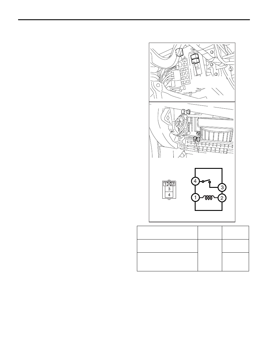
REAR WINDOW DEFOGGER RELAY 
CHECK

M1540500600279

Battery voltage

Terminal 
number

Normal 
condition

At no energisation

− 3

No 
continuity

With current supply 
[terminal 1 (+), terminal 2 
(

−)]

Continuity 
exists (2 

Ω 

or less)

AC802143

AC612289

AB

Rear window
defogger relay

Rear window
defogger relay

<LHD>

<RHD>

ETACS

CHASSIS ELECTRICAL

54A-515

ETACS

SPECIAL TOOLS

M1545000600172

ETACS

CHASSIS ELECTRICAL

54A-516

Tool

Number

Name

Use

MB991955

a. MB991824
b. MB991827
c. MB991910
d. MB991911
e. MB991825
f. MB991826

M.U.T.-III sub-
assembly

a. Vehicle 

Communication 
Interface (V.C.I.)

b. M.U.T.-III USB 

cable

c. M.U.T.-III main 

harness A 
(Vehicles with CAN 
communication 
system)

d. M.U.T.-III main 

harness B 
(Vehicles without 
CAN 
communication 
system)

e. M.U.T.-III measure 

adapter

f. M.U.T.-III trigger 

harness

CAUTION

For vehicles with CAN 
communication, use M.U.T.-III 
main harness A to send 
simulated vehicle speed. If you 
connect M.U.T.-III main harness 
B instead, the CAN 
communication does not 
function correctly.
ETACS-ECU check (Diagnosis 
code, service data)

MB991910

MB991826

MB991955

MB991911

MB991824

MB991827

MB991825

a

b

c

d

e

f

DO NOT USE

ETACS

CHASSIS ELECTRICAL

54A-517

TROUBLESHOOTING

STANDARD FLOW OF DIAGNOSTIC 
TROUBLESHOOTING

M1545000900139

Refer to GROUP 00 

− Contents of troubleshooting .

DIAGNOSIS FUNCTION

M1545001000203

HOW TO READ DIAGNOSIS CODE

Refer to GROUP 00 

− Diagnosis function .

HOW TO ERASE DIAGNOSIS CODE

Refer to GROUP 00 

− Diagnosis function .

CHECK OF FREEZE FRAME DATA

The freeze frame data can be checked by using the 
M.U.T.-III.
When detecting fault and storing the diagnosis code, 
the ECU connected to CAN bus line obtains the data 
before the determination of the diagnosis code and 
the data when the diagnosis code is determined, and 
then stores the ECU status of that time. By analysing 
each data from M.U.T.-III, the troubleshooting can be 
performed more efficiently. The displayed items are 
as the table below.

MB991499

Measurement probe

Measurements of voltage and 
resistance value
NOTE: M.U.T.-II attached probe 
(Commercial probes can also be 
used.)

MB991223

a. MB991219
b. MB991220
c. MB991221
d. MB991222

Harness set

a. Check harness
b. LED harness
c. LED harness 

adapter

d. Probe

Continuity check and voltage 
measurement at harness wire or 
connector

a. For checking connector pin 

contact pressure

b. For checking power supply 

circuit

c. For checking power supply 

circuit

d. For connecting a locally 

sourced tester

MB992006

Extra fine probe

Continuity check and voltage 
measurement at harness wire or 
connector

Tool

Number

Name

Use

MB991499

MB991223

a

d

c

b

DO NOT USE

BA

MB992006


Content   ..  211  212  213  214   ..