Mitsubishi Lancer (4A9 engine). Manual - part 186


  Index      Mitsubishi     Mitsubishi Lancer (4A9 engine) 12GS41 & 44S - service repair manual


Search            


Content   ..  184  185  186  187   ..


Mitsubishi Lancer (4A9 engine). Manual - part 186


MITSUBISHI MULTI COMMUNICATION SYSTEM (MMCS)

CHASSIS ELECTRICAL

54A-406

DIAGNOSIS PROCEDURE

STEP 1. Confirmation in MMCS service mode
Check the items below in the MMCS service mode 
(Refer to ).

•  Perform "Network/Connect Line Check" in the 

MMCS service mode to check that the communi-
cation and wire connection with the GPS are in 
good condition.

•  Perform "Vehicle Signal Check", and then check 

the status of the vehicle speed signal. 

•  Perform "Sensor Check", and then check the 

status of the vehicle speed sensor and the gyro 
sensor.

Q: Is the check result normal?

YES (OK for all) : 

Go to Step 6.

NO <GPS is not OK> : 

Go to Step 2.

NO <The vehicle speed sensor is not OK, or vehicle 
speed pulse does not increase after starting from a 
standstill> : 

Go to Step 3.

NO <Gyro sensor is not OK> : 

Go to Step 6.

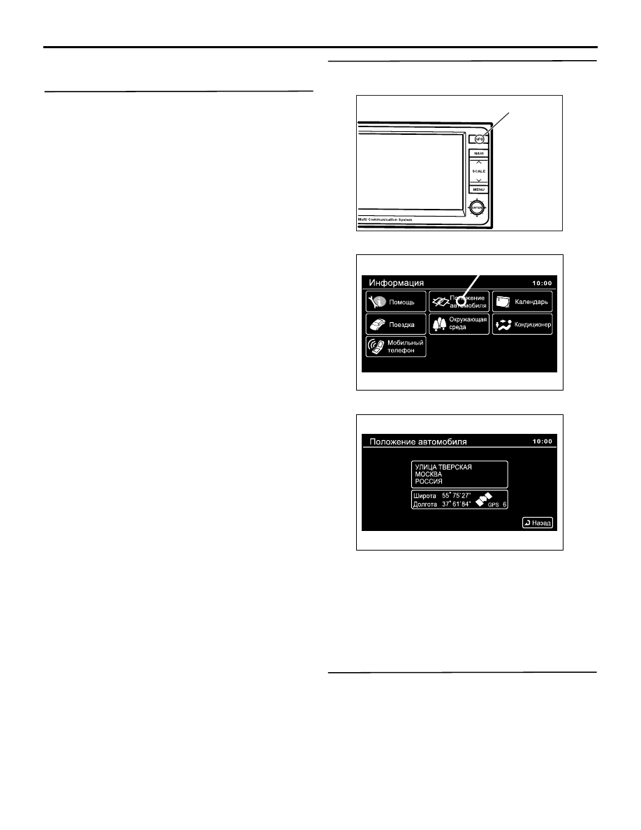
STEP 2. GPS reception check
(1) Start the multivision display.

(2) Press the (1).

(3) Select (2).

(4) Wait for 5 minutes, and then check whether GPS 

signal can be received.

Q: Is the check result normal?

YES : 

Go to Step 6.

NO : 

Perform Inspection Procedure 7 "GPS 
signal cannot be received" (Refer to .), and 
then go to Step 6. 

STEP 3. Check the speedometer.
Check whether the speedometer works normally. 
(Refer to .)

Q: Does the speedometer work normally?

YES : 

Go to Step 4.

NO : 

Diagnose the combination meter (Refer to 
Combination meter 

− Troubleshooting ).

AC804201

(1)

AB

AC803907

AB

(2)

AC803908

MITSUBISHI MULTI COMMUNICATION SYSTEM (MMCS)

CHASSIS ELECTRICAL

54A-407

STEP 4. Connector check: C-01 combination 
meter connector, C-144 multivision display 
connector

Q: Is the check result normal?

YES : 

Go to Step 5.

NO : 

Repair the defective connector.

STEP 5. Check the harness wire between C-01 
combination meter connector terminal No.20 and 
C-144 multivision display connector terminal 
No.13.

• Check the signal line for open and short circuit.

NOTE: Prior to the wiring harness inspection, check 
intermediate connector C-139, and repair if neces-
sary.

Q: Is the check result normal?

YES : 

Go to Step 6.

NO : 

Repair the wiring harness.

STEP 6. Check of the troubles
Drive the vehicle for some time with the GPS signals 
being received, and check if the own vehicle mark is 
dislocated.

Q: Is the check result normal?

YES : 

The trouble can be an intermittent 

malfunction (Refer to GROUP 00 

− How to 

use Troubleshooting/inspection Service 
Points 

− How to Cope with Intermittent 

Malfunction ).

NO : 

Replace the multivision display.

MITSUBISHI MULTI COMMUNICATION SYSTEM (MMCS)

CHASSIS ELECTRICAL

54A-408

Inspection Procedure 6: The FM/MW/LM radio broadcasting can not be received.

CAUTION

Whenever the multivision display is replaced, 
ensure that the power supply circuit and the 
earthing circuit are normal. (Check that the volt-
age is 10 V or more.)

COMMENTS ON TROUBLE SYMPTOM
In case of FM/MW/LW radio broadcasting can not be 
received., the roof antenna (antenna rod, antenna 
base), antenna fender or multivision display may 
have a problem.

ROOF ANTENNA

ANTENNA 

FEEDER CABLE

ANTENNA AMPLIFIER

Antenna Circuit

MULTIVISION DISPLAY

Wire colour code 
B : Black     LG : Light green     G : Green     L : Blue     W : White     Y : Yellow     SB : Sky blue 
BR : Brown     O : Orange     GR : Grey     R : Red     P : Pink     V : Violet     PU : Purple     SI : Silver

AC801696

Connectors: C-09, C-141 <LHD>

AG

C-09

C-141

AC801699AH

Connectors: C-09, C-141 <RHD>

C-09

C-141

MITSUBISHI MULTI COMMUNICATION SYSTEM (MMCS)

CHASSIS ELECTRICAL

54A-409

NOTE: The radio wave may not be received if the 
vehicle is placed in the area which is exposed to a 
special electric field. Thus, check that the radio 
broadcasting can be received using the radio of 
another vehicle before carrying out diagnosis.

PROBABLE CAUSES

• Malfunction of roof antenna (antenna rod, 

antenna base)

• Antenna feeder malfunction

• Malfunctions of multivision display

DIAGNOSIS PROCEDURE

STEP 1. Check the state of the roof antenna.

Q: Is the roof antenna assembled?

YES : 

Go to Step 2.

NO : 

Assemble the antenna.

STEP 2. Check to see if inspections are taking 
place is an area exposed to special electric 
fields.

Q: Is the reception area exposed to special electric 

fields?
YES : 

Go to Step 3.

NO : 

Go to Step 4.

STEP 3. Move the vehicle and check the radio.
Move the vehicle to a good reception area that is not 
exposed to special electric fields.

Q: Is the check result normal?

YES : 

Diagnosis complete.

NO : 

Go to Step 4.

STEP 4. Check damage in the roof antenna (the 
antenna rod, the antenna base).

Q: Is the check result normal?

YES : 

Go to Step 5.

NO : 

Replace antenna rod or antenna base.

STEP 5. Check the connection of the antenna 
plug and multivision display.

Q: Is the check result normal?

YES : 

Go to Step 6.

NO : 

Thoroughly connect the antenna plug and 
the multivision display. 

STEP 6. Connector check: C-141 multivision 
display connector, C-09 antenna amplifier 
(antenna base) connector

Q: Is the check result normal?

YES : 

Go to Step 7.

NO : 

Repair or replace the damaged connector.

STEP 7. Check the antenna feeder between C-141 
multivision display connector terminal No.81 and 
C-09 antenna amplifier (antenna base) connector 
terminal No.2.

• Check the signal line for open circuit and short 

circuit.

NOTE: Prior to the wiring harness inspection, inter-
mediate connector C-139, and repair if necessary.

Q: Is the check result normal?

YES : 

Go to Step 8.

NO : 

Repair the antenna feeder. 

STEP 8. Substitute a known good multivision 
display, and check the trouble symptom.

Q: Is the check result normal?

YES : 

Replace the multivision display.

NO : 

Either repair or replace the roof antenna 
assembly. 

Inspection Procedure 7: GPS signal can not be received. <Except vehicles for RUSSIA>

CAUTION

Whenever the multivision display is replaced, 
ensure that the power supply circuit and the 
earthing circuit are normal. (Check that the volt-
age is 10 V or more.)
COMMENTS ON TROUBLE SYMPTOM
The GPS antenna or the multivision display may be 
defective.

PROBABLE CAUSES

• Malfunctions of GPS antenna

• Malfunctions of multivision display


Content   ..  184  185  186  187   ..