Mitsubishi Lancer (4A9 engine). Manual - part 184
MITSUBISHI MULTI COMMUNICATION SYSTEM (MMCS)
CHASSIS ELECTRICAL
54A-398
COMMENTS ON TROUBLE SYMPTOM
If the sound is not heard from one of the speakers,
the speaker, multivision display, audio amplifier, com-
munication line from the multivision display to the
audio amplifier, or communication line from the audio
amplifier to the speaker may have a problem. Also,
the option coding information may be inconsistent.
PROBABLE CAUSES
• Malfunction of speaker
• Malfunctions of multivision display
• Malfunction of audio amplifier
• Option coding information inconsistency
• Damaged harness wires and connectors
DIAGNOSIS PROCEDURE
STEP 1. ETACS-ECU coding data check
(1) Operate the M.U.T.-III to read the ETACS-ECU
option coding information (Refer to GROUP 00
−
Coding Table ).
(2) Check that the "Number of speaker" is set to
"Premium."
Q: Is the check result normal?
YES :
Go to Step 2.
NO :
Operate the M.U.T.-III to set the option
coding "Number of speaker" to "Premium,"
and check the trouble symptom.
STEP 2. Check the MMCS service mode, CAN
communication confirmation and coding data
(1) Display the CAN communication confirmation
and coding data for the MMCS service mode.
(Refer to )
(2) Check if "PREMIUM" is displayed.
Q: Is the check result normal?
YES :
Go to Step 3.
NO :
Go to Step 4.
STEP 3. Check the service data log for the MMCS
service mode.
Display the service data log for the MMCS service
mode and check if the service data log for the SP
(speaker) is displayed. (Refer to .)
Q: Is the service data log for the SP (speaker)
displayed?
YES :
Go to Step 4.
NO :
Go to Step 7.
STEP 4. M.U.T.-III CAN bus diagnostics
Use the M.U.T.-III to diagnose the CAN bus lines.
Q: Is the check result normal?
YES :
Go to Step 5.
NO :
Repair the CAN bus line.
STEP 5. Check whether the diagnosis code is set.
Check if the diagnosis code is set to the CAN box
unit.
(1) Erase the diagnosis code.
(2) Turn the ignition switch from "LOCK" (OFF)
position to "ON" position.
(3) Check if diagnosis code is set.
Q: Is the diagnosis code set?
YES :
Troubleshoot the MMCS (Refer to ).
NO :
Go to Step 6.
STEP 6. M.U.T.-III other system diagnosis code
Check if the diagnosis code is set to the ETACS-
ECU.
Q: Is the diagnosis code set?
YES :
Diagnose the ETACS-ECU (Refer to
GROUP 54A
− ETACS-ECU −
Troubleshooting ).
NO :
Go to Step 7.
STEP 7. Checking with audio speaker check
Perform the audio speaker check, and check which
speaker does not output the sound (Refer to ).
NOTE: In the following procedure, check the
speaker, tweeter or subwoofer that is abnormal.
Q: Is the check result normal?
YES (normal for all) :
The trouble can be an
intermittent malfunction (Refer to GROUP
00
− How to use Troubleshooting/inspection
Service Points
− How to Cope with
Intermittent Malfunction ).
NO (Either a speaker, a tweeter or a subwoofer is
abnormal) :
Go to Step 8.
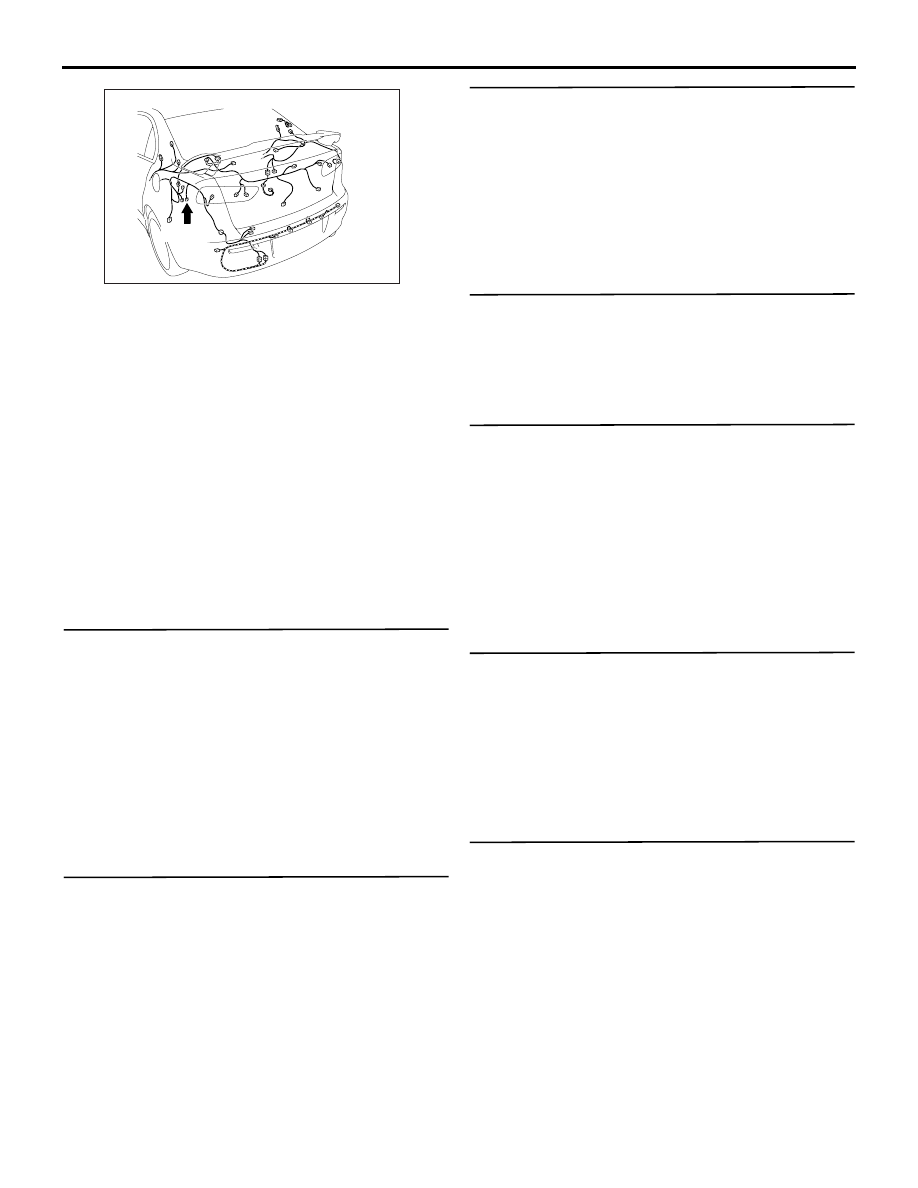
AC701264 AR
Connector: F-25 <LANCER>
F-25 (B)