Mitsubishi Lancer (4A9 engine). Manual - part 127
REAR COMBINATION LAMP
CHASSIS ELECTRICAL
54A-170
STEP 4. Wiring harness check between the A-53
headlamp assembly (RH) connector terminal No.
6, F-08 rear combination lamp (RH) connector
terminal No. 1 or F-09 tail lamp (RH) <LANCER>
connector terminal No. 1 and the body earth
NOTE: Prior to the wiring harness inspection, check
intermediate connector F-28, and repair if necessary.
• Check the earth wires for open circuit.
Q: Is the check result normal?
YES :
Go to Step 7.
NO :
Repair the wiring harness.
STEP 5. Connector check: C-304 and C-311
ETACS-ECU connector
Q: Is the check result normal?
YES :
Go to Step 6.
NO :
Repair the defective connector.
STEP 6. Wiring harness check between the A-53
headlamp assembly (RH) connector terminal No.
4, F-08 rear combination lamp (RH) connector
terminal No. 3 or F-09 tail lamp (RH) <LANCER>
connector terminal No. 2 and C-304 ETACS-ECU
connector terminal No. 7 or C-311 ETACS-ECU
connector terminal No. 13
NOTE: Prior to the wiring harness inspection, check
intermediate connector D-12, D-16 and F-28, and
repair if necessary.
• Check the power supply lines for open circuit and
short circuit.
Q: Is the check result normal?
YES :
Go to Step 7.
NO :
Repair the wiring harness.
STEP 7. Check whether the diagnosis code is
reset.
(1) Erase the diagnosis code.
(2) Turn the ignition switch from "LOCK" (OFF)
position to "ON" position.
(3) Check if diagnosis code is set.
Q: Is the diagnosis code set?
YES :
Replace the ETACS-ECU.
NO :
The diagnosis is complete.
Code No.B16A8 Tail lamp (LH) circuit short <Short circuit in the position lamp (LH) circuit, tail lamp
(LH) circuit or the licence plate lamp circuit>
ACA00916
AF
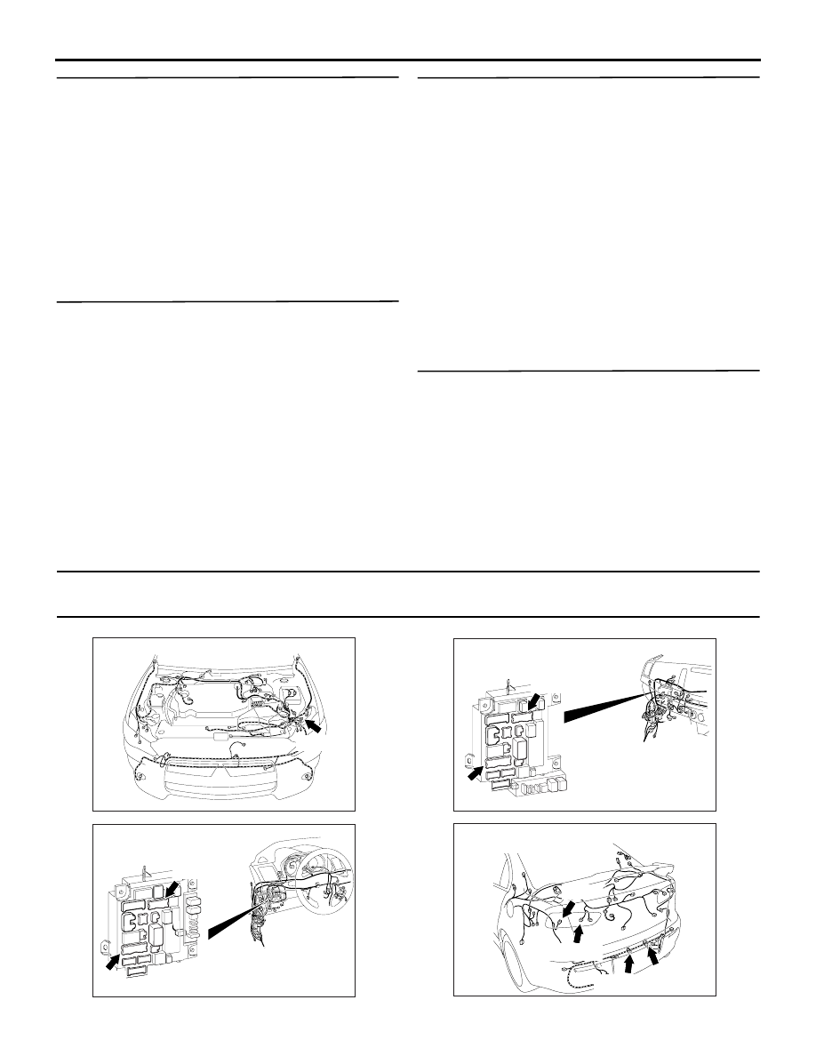
Connector: A-35
A-35 (B)
ACA00886
BC
Connectors: C-304, C-311 <LHD>
ETACS-ECU
C-304
C-311
ACA00887
BD
Connectors: C-304, C-311 <RHD>
ETACS-ECU
C-304
C-311
ACA00901AF
F-23
F-22 (GR)
F-15 (GR)
F-13 (GR)
Connectors: F-13, F-15, F-22, F-23 <LANCER>