Mitsubishi Lancer (4A9 engine). Manual - part 119


  Index      Mitsubishi     Mitsubishi Lancer (4A9 engine) 12GS41 & 44S - service repair manual


Search            


Content   ..  117  118  119  120   ..


Mitsubishi Lancer (4A9 engine). Manual - part 119


HEADLAMP

CHASSIS ELECTRICAL

54A-138

LIGHTING CONTROL SENSOR REMOVAL AND INSTALLATION

M1540108500148

REMOVAL SERVICE POINT

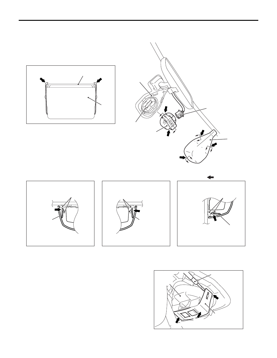
<<A>> LIGHTING CONTROL SENSOR REMOVAL

While pushing the clamp to the windshield side, pry 
up the clamp to disengage the right and left claws 

using the screwdriver (

−), and then remove the light-

ing control sensor.

AC709856AB

1

Note
         : Claw positions

Section A - A

Section B - B

Section C - C

Section D - D

Optical coupler

3

D

C

B

D

C

1

1

1

Claw

Claw

Lighting control
sensor bracket

Lighting control
sensor bracket

Lighting control
sensor bracket

Lighting control
sensor bracket

Claw

Claw

Claw

Optical coupler

2

3

A

A

B

Removal Steps 

1.

Lighting control sensor cover

2.

Connector

<<

A

>>

>>

A

<<

3.

Lighting control sensor

AC700066

Screwdriver (-)

AD

Claw

Lighting
control
sensor

Clamp

Push

Push

HEADLAMP

CHASSIS ELECTRICAL

54A-139

INSTALLATION SERVICE POINT

>>A<< LIGHTING CONTROL SENSOR INSTALLA-
TION

CAUTION

After executing the lighting control sensor (rain 
sensor) adaptation, do not touch the lighting 
control sensor (or do not move it from the fixed 
position).

• Mount the lighting control sensor onto the optical 

coupler, and then connect the connector.

• When reusing the lighting control sensor or when 

the lighting control sensor is pushed to check the 
installation condition, install the connector and 
the lighting control sensor cover and wipe the 
windshield thoroughly. When the windshield is 
dry, execute the lighting control sensor (rain sen-
sor) adaptation. <Refer to GROUP 51 

− Lighting 

Control Sensor (Rain Sensor) Adaptation >.

NOTE: Be careful not to touch the lighting control 
sensor receiver. (The lighting control sensor receiver 
has limited resistance to oil.)

INSPECTION

HEADLAMP RELAY CHECK

M1540104000185

HEADLAMP RELAY (LO) CHECK

HEADLAMP RELAY (HI) CHECK

AC700034

2

3

4

1

AB

Headlamp relay (LO)

Battery voltage

Terminal 
number

Normal 
condition

At no energisation

− 4

No 
continuity

With current supply 
[terminal 2 (+), terminal 1 
(

−)]

Continuity 
exists (2 

Ω 

or less)

Battery voltage

Terminal 
number

Normal 
condition

At no energisation

− 4

No 
continuity

With current supply 
[terminal 2 (+), terminal 1 
(

−)]

Continuity 
exists (2 

Ω 

or less)

AC700034

2

3

4

1

AC

Headlamp relay (HI)

HEADLAMP

CHASSIS ELECTRICAL

54A-140

HEADLAMP LEVELLING SWITCH CHECK 
<VEHICLES WITH HEADLAMP MANUAL 
LEVELLING SYSTEM>

M1540101300187

LIGHTING CONTROL SENSOR (LAMP 
SENSOR) CHECK

M1540109000146

Use M.U.T.-III to check the LIN data list as follows.
1. Under the direct sunlight, turn the ignition switch 

to the ON position, and turn the lighting switch to 
the auto lamp position.

2. When the lighting control sensor receiver is 

covered to be darkened, it is judged normal if the 
items of No. 7009: RLS Low beam "ON" request 
and 7011: RLS Taillamp "ON" request change 
from OFF to ON.

NOTE: 

.

When covering the lighting control sensor 
receiver, be careful not to touch the windshield 
surface (where the lighting control sensor 
receiver is mounted). (The lighting control sensor 
receiver has limited resistance to oil.)

Before checking the data list by using M.U.T.-III, 
wipe the windshield thoroughly and visually 
check if there are foreign materials on the wind-
shield to which the lighting control sensor is 
installed.

BRACKET REPAIR OF HEADLAMP 
ASSEMBLY

M1540104500102

CAUTION

• If damage is present to locations other than 

the repairable bracket, replace the assembly.

• Apply a tape to the area around the damaged 

bracket to prevent damage.

• During repair work, be careful not to damage 

the repair bracket installation bosses.

When brackets A, B and C shown in the figure are 
damaged, a low-cost repair can be performed by 
mounting a repair bracket.

OPERATIONS BEFORE REPAIRING 
BRACKET

Remove the headlamp assembly.

REPAIR PROCEDURE OF BRACKET A

1. Cut the damaged bracket A so that it has the 

larger dimension than the dimension shown in the 
figure from the mounting boss seating face.

Measured 
terminals

Switch 
position

Resistance value 

− 6

0

750

1

1,110

2

1,470

3

1,830

4

2,190

− 6

0, 1, 2, 3, 4

2,810

AC700633AB

AC802176AB

Bracket C

Bracket A

Bracket B

AC802177AB

Damage bracket A

;;;;

;;;;

AC802178AB

13.5 mm or more

5.0 mm or more

HEADLAMP

CHASSIS ELECTRICAL

54A-141

2. Smoothen the bracket cut surface using the 

sandpaper.

3. Fix the repair bracket A to the headlamp assembly 

using the tapping screw.

REPAIR PROCEDURE OF BRACKET B

1. Cut off the damaged bracket B.

2. Remove the remaining bracket cut surface using 

the sandpaper.

3. Fix the repair bracket B to the headlamp assembly 

using the tapping screw.

REPAIR PROCEDURE OF BRACKET C

1. Cut the damaged bracket C so that it has the 

dimension shown in the figure. 

2. Smoothen the bracket cut surface using the 

sandpaper.

3. Fix the repair bracket C to the headlamp 

assembly using the tapping screw.

OPERATIONS AFTER REPAIRING 
BRACKET

1. Mount the headlamp assembly to the vehicle.
2. Check that the headlamp assembly does not 

vibrate during driving.

3. Check whether each lamp built in the headlamp 

assembly and the headlamp levelling system are 
properly operated.

AC802179AB

Tapping 
screw

Repair bracket A

AC802180AB

Damage bracket B

;;;

;;

;

;;

;;

AC802181

AC802182 AB

Tapping 
screw

Repair bracket B

AC802183AB

Damage bracket C

;;;

;;;

AC802184AB

42 mm or more

12 mm or less

AC802185AB

Tapping 
screw

Repair bracket C


Content   ..  117  118  119  120   ..