Mitsubishi Lancer (4A9 engine). Manual - part 77
 

  Index      Mitsubishi     Mitsubishi Lancer (4A9 engine) 12GS41 & 44S - service repair manual


Search            


Content   ..  75  76  77  78   ..


Mitsubishi Lancer (4A9 engine). Manual - part 77


TROUBLESHOOTING

ACTIVE STABILITY CONTROL SYSTEM (ASC)

35C-161

STEP 3. Connector check: A-58 ASC-ECU 
connector, C-128 intermediate connector, C-212 
ignition switch connector, C-309 ETACS-ECU 
connector, C-315 ETACS-ECU connector, C-317 
ETACS-ECU connector

Q: Is the check result normal?

YES : 

Go to Step 4.

NO  : 

Repair the damaged connector.

STEP 4. Fusible link check: Check the fusible link 
No.27.

Q: Is the check result normal?

YES : 

Go to Step 6.

NO : 

Go to Step 5.

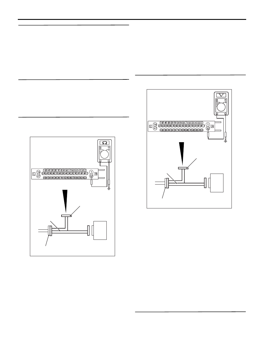
STEP 5. Resistance measurement at A-58 ASC-
ECU connector
(1) Removal the fusible link No.27.

AC606869 HE

ASC-ECU

MB991997

Check harness

A-58 ASC-ECU
harness connector

(2) Disconnect the ASC-ECU connector, connect 

special tool ASC check harness (MB991997) to 
the harness-side connector, and then measure 
the resistance at the special tool connector side.
NOTE: Do not connect the special tool ASC 
check harness (MB991997) to ASC-ECU.

(3) Measure the resistance between the terminal 

No.32 and the body earth.

OK: No continuity

Q: Is the check result normal?

YES : 

Replace the fusible link No.27. Then go to 

Step 24.

NO : 

The short circuit may be present in the 
power supply circuit. Repair the wiring 
harness between the A-58 ASC-ECU 
connector terminal No.32 and the fusible 
link No.27, and then replace the fusible link 
No.27. Then go to Step 24.

STEP 6. Voltage measurement at the A-58 ASC-
ECU connector

AC606869DG

ASC-ECU

MB991997

Check harness

A-58 ASC-ECU
harness connector

(1) Disconnect the ASC-ECU connector, connect 

special tool ASC check harness (MB991997) to 
the harness-side connector, and then measure 
the voltage at the special tool connector side.
NOTE: Do not connect the special tool ASC 
check harness (MB991997) to ASC-ECU.

(2) Measure the voltage between terminal No.32 and 

body earth.

OK: Approximately system voltage

Q: Is the check result normal?

YES : 

Go to Step 7.

NO : 

The open circuit may be present in the 
power supply circuit. Repair the wiring 
harness between the A-58 ASC-ECU 
connector terminal No.32 and the fusible 
link No.27. Then go to Step 24.

STEP 7. Check the fusible link No.26.

Q: Is the check result normal?

TROUBLESHOOTING

ACTIVE STABILITY CONTROL SYSTEM (ASC)

35C-162

YES : 

Go to Step 9.

NO : 

Go to Step 8.

STEP 8. Resistance measurement at A-58 ASC-
ECU connector
(1) Removal the fusible link No.26.

AC606869LC

ASC-ECU

MB991997

Check harness

A-58 ASC-ECU
harness connector

(2) Disconnect the ASC-ECU connector, connect 

special tool ASC check harness (MB991997) to 
the harness-side connector, and then measure 
the resistance at the special tool connector side.
NOTE: Do not connect the special tool ASC 
check harness (MB991997) to ASC-ECU.

(3) Measure the resistance between the terminal 

No.1 and the body earth.

OK: No continuity

Q: Is the check result normal?

YES : 

Replace the fusible link No.26. Then go to 

Step 24.

NO : 

The short circuit may be present in the 
power supply circuit. Repair the wiring 
harness between the A-58 ASC-ECU 
connector terminal No.1 and the fusible link 
No.26, and then replace the fusible link 
No.26. Then go to Step 24.

STEP 9. Voltage measurement at the A-58 ASC-
ECU connector

AC606869LD

ASC-ECU

MB991997

Check harness

A-58 ASC-ECU
harness connector

(1) Disconnect the ASC-ECU connector, connect 

special tool ASC check harness (MB991997) to 
the harness-side connector, and then measure 
the voltage at the special tool connector side.
NOTE: Do not connect the special tool ASC 
check harness (MB991997) to ASC-ECU.

(2) Measure the voltage between terminal No.1 and 

body earth.

OK: Approximately system voltage

Q: Is the check result normal?

YES : 

Go to Step 10.

NO : 

The open circuit may be present in the 
power supply circuit. Repair the wiring 
harness between the A-58 ASC-ECU 
connector terminal No.1 and the fusible link 
No.26. Then go to Step 24.

STEP 10. Check the fuse No.12.
Visually check for open circuit in fuse No.12.

Q: Is the check result normal?

YES : 

Go to Step 12.

NO : 

Go to Step 11.

TROUBLESHOOTING

ACTIVE STABILITY CONTROL SYSTEM (ASC)

35C-163

STEP 11. Resistance measurement at A-58 ASC-
ECU connector
(1) Disconnect the C-317 ETACS-ECU connector.

AC606869HF

ASC-ECU

MB991997

Check harness

A-58 ASC-ECU
harness connector

(2) Disconnect the ASC-ECU connector, connect 

special tool ASC check harness (MB991997) to 
the harness-side connector, and then measure 
the resistance at the special tool connector side.
NOTE: Do not connect the special tool ASC 
check harness (MB991997) to ASC-ECU.

(3) Measure the resistance between the terminal 

No.8 and the body earth.

OK: No continuity

Q: Is the check result normal?

YES : 

Replace the fuse No.12. Then go to Step 

24.

NO : 

The short circuit may be present in the 
power supply circuit. Repair the wiring 
harness between the A-58 ASC-ECU 
connector terminal No.8 and the C-317 
ETACS-ECU connector terminal No.5, and 
then replace the fuse No.12. Then go to 
Step 24.

STEP 12. Check the fuse No.17.
Visually check for open circuit in fuse No.17.

Q: Is the check result normal?

YES : 

Go to Step 14.

NO : 

Go to Step 13.

STEP 13. Resistance measurement at A-58 ASC-
ECU connector
(1) Disconnect the C-315 ETACS-ECU connector.

AC606869 HH

ASC-ECU

MB991997

Check harness

A-58 ASC-ECU
harness connector

(2) Disconnect the ASC-ECU connector, connect 

special tool ASC check harness (MB991997) to 
the harness-side connector, and then measure 
the resistance at the special tool connector side.
NOTE: Do not connect the special tool ASC 
check harness (MB991997) to ASC-ECU.

(3) Measure the resistance between the terminal 

No.2 and the body earth.

OK: No continuity

Q: Is the check result normal?

YES : 

Replace the fuse No.17. Then go to Step 

24.

NO : 

The short circuit may be present in the 
power supply circuit. Repair the wiring 
harness between the A-58 ASC-ECU 
connector terminal No.2 and the C-315 
ETACS-ECU connector terminal No.4, and 
then replace the fuse No.17. Then go to 
Step 24.

STEP 14. Measure the voltage at the C-309 
ETACS-ECU connector.
(1) Disconnect the connector, and measure at the 

wiring harness-side connector.

(2) Measure the voltage between the terminal No.1 

TROUBLESHOOTING

ACTIVE STABILITY CONTROL SYSTEM (ASC)

35C-164

and the body earth.

OK: Approximately system voltage

Q: Is the check result normal?

YES : 

Go to Step 17.

NO : 

Go to Step 15.

STEP 15. Fusible link check: Check the fusible 
link No.34 <PETROL> or No.44 <DIESEL>.

Q: Is the check result normal?

YES : 

Go to Step 17.

NO : 

Go to Step 16.

STEP 16. Resistance measurement at C-309 
ETACS-ECU connector
(1) Removal the fusible link No.34 <PETROL> or 

No.44 <DIESEL>.

(2) Disconnect the C-309 ETACS-ECU connector, 

and then measure the resistance at the 
connector side.

(3) Measure the resistance between the terminal 

No.1 and the body earth.

OK: No continuity

Q: Is the check result normal?

YES : 

Replace the fusible link No.34 <PETROL> 

or No.44 <DIESEL>. Then go to Step 24.

NO : 

The short circuit may be present in the 
power supply circuit. Repair the wiring 
harness between the C-309 ETACS-ECU 
connector terminal No.1 and the fusible link 
No.34 <PETROL> or No.44 <DIESEL>, and 
then replace the fusible link No.34 
<PETROL> or No.44 <DIESEL>. Then go to 
Step 24.

STEP 17. Resistance measurement at fusible link 
No.34 <PETROL> or No.44 <DIESEL> and C-309 
ETACS-ECU connector
(1) Disconnect the C-309 ETACS-ECU connector 

and fusible link No.34 <PETROL> or No.44 
<DIESEL>, and then measure the resistance at 
the harness connector side.

(2) Measure the resistance between the fusible link 

No.34 <PETROL> or No.44 <DIESEL> and C-
309 ETACS-ECU connector terminal No.1.

OK: Continuity exists (2 

 or less)

Q: Is the check result normal?

YES : 

Go to Step 18.

NO : 

The open circuit may be present in the 
power supply circuit. Repair the wiring 
harness between the fusible link No.34 
<PETROL> or No.44 <DIESEL> and C-309 
ETACS-ECU connector terminal No.1. Then 
go to Step 24.

STEP 18. Resistance measurement at A-58 ASC-
ECU connector
(1) Disconnect the C-317 ETACS-ECU connector.

AC606869 HG

ASC-ECU

MB991997

Check harness

A-58 ASC-ECU
harness connector

Connector: C-317
(harness side)

(2) Disconnect the A-58 ASC-ECU connector, 

connect special tool ASC check harness 
(MB991997) to the harness-side connector, and 
then measure the resistance at the special tool 
connector side.
NOTE: Do not connect the special tool ASC 
check harness (MB991997) to ASC-ECU.

(3) Measure the resistance between the A-58 ASC-

ECU connector terminal No.8 and the C-317 
ETACS-ECU connector terminal No.5.

OK: Continuity exists (2 

 or less)

Q: Is the check result normal?

YES : 

Go to Step 19.

NO : 

The open circuit may be present in the 
power supply circuit. Repair the wiring 
harness between the A-58 ASC-ECU 
connector terminal No.8 and the C-317 
ETACS-ECU connector terminal No.5. Then 
go to Step 24.


Content   ..  75  76  77  78   ..