Mitsubishi Lancer (4A9 engine). Manual - part 66
AC612705
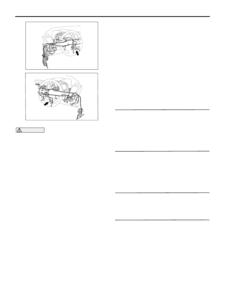
Connector: C-137 <LHD>
CG
C-137 (B)
AC701122
Connector: C-137 <RHD>
BL
TROUBLESHOOTING
ACTIVE STABILITY CONTROL SYSTEM (ASC)
35C-117
CAUTION
• If there is any problem in the CAN bus lines,
an incorrect diagnosis code may be set. Prior
to this diagnosis, diagnose the CAN bus lines
(Refer to GROUP 54C
− CAN Bus Diagnostics
Table ).
• Whenever ECU is replaced, ensure that the
CAN bus lines are normal.
• Do not drop or shock the G and yaw rate sen-
sor.
• When the G and yaw rate sensor is replaced,
always carry out calibration to make ASC-
ECU learn the neutral point (Refer to
• When the hydraulic unit (integrated with ASC-
ECU) is replaced, always carry out the calibra-
tion of the steering wheel sensor, the G and
yaw rate sensor and brake fluid pressure sen-
sor (Refer to
and
OPERATION
• ASC-ECU supplies power to the G and yaw rate
sensor at the terminal No.1.
• The G and yaw rate sensor outputs the signal to
ASC-ECU via the special CAN bus lines.
DIAGNOSIS CODE SET CONDITIONS
This diagnosis code is set if any malfunction below is
found:
Code No. C2114
• When the power supply voltage applied from
ASC-ECU to the G and yaw rate sensor is not
within the standard value range <low voltage (6.5
± 0.5 V or less)>
Code No. C2115
• When the power supply voltage applied from
ASC-ECU to the G and yaw rate sensor is not
within the standard value range <high voltage
(18.0
± 1.0 V or more)>
PROBABLE CAUSES
• Damaged wiring harness and connectors
• G and yaw rate sensor malfunction
• ASC-ECU malfunction
DIAGNOSIS PROCEDURE
STEP 1. M.U.T.-III CAN bus diagnosis
Use M.U.T.-III to diagnose the CAN bus lines.
Q: Is the check result normal?
YES :
Go to Step 2.
NO :
Repair the CAN bus lines (Refer to GROUP
54C
− CAN Bus Diagnostics Table ). On
completion, go to Step 2.
STEP 2. M.U.T.-III diagnosis code
Check that the diagnosis code No.U0125 is set in
ASC-ECU.
Q: Is the diagnosis code No.U0125 set?
YES :
Troubleshoot for the diagnosis code (Refer
to
NO :
Go to Step 3.
STEP 3. Diagnosis code recheck
Q: Are the diagnosis codes No. C2114 or C2115 set?
YES :
Go to Step 4.
NO :
This diagnosis is complete.
STEP 4. M.U.T.-III data list
Check the following data list (Refer to
• Item 08: Lateral G sensor
• Item 09: G sensor
• Item 12: Yaw rate sensor
Q: Is the check result normal?
YES :
Go to Step 12.
NO :
Go to Step 5.