Mitsubishi Lancer (4A9 engine). Manual - part 65


  Index      Mitsubishi     Mitsubishi Lancer (4A9 engine) 12GS41 & 44S - service repair manual


Search            


Content   ..  63  64  65  66   ..


Mitsubishi Lancer (4A9 engine). Manual - part 65


TROUBLESHOOTING

ACTIVE STABILITY CONTROL SYSTEM (ASC)

35C-113

YES : 

Replace the hydraulic unit (integrated with 

ASC-ECU) (Refer to 

P.35C-185

), and then 

go to Step 13.

NO : 

Intermittent malfunction (Refer to GROUP 
00 

− How to Use Troubleshooting/How to 

Cope with Intermittent Malfunctions ).

STEP 13. Check whether the diagnosis code is 
reset.
(1) Erase the diagnosis code.
(2) Drive the vehicle at 20 km/h or higher.

Q: Is the diagnosis code No.C123C set?

YES : 

Return to Step 1.

NO : 

This diagnosis is complete.

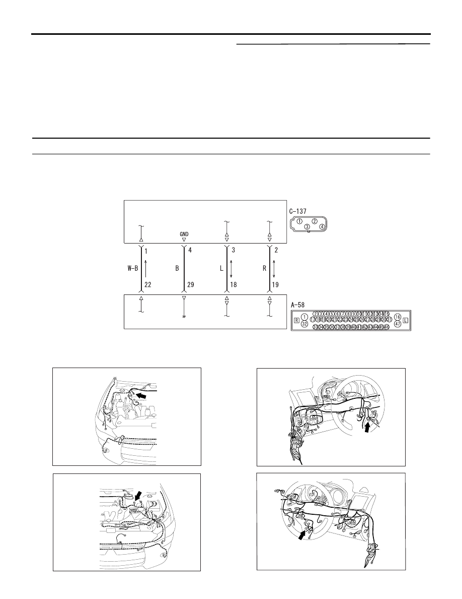
Code No. C2204 Internal abnormality in G and yaw rate sensor

G and Yaw Rate Sensor Circuit

G AND YAW RATE SENSOR

ASC-ECU

Wire colour code 
B : Black     LG : Light green     G : Green     L : Blue     W : White     Y : Yellow     SB : Sky blue 
BR : Brown     O : Orange     GR : Grey     R : Red     P : Pink     V : Violet     PU : Purple     SI : Silver

ACB02567

AC612691

AO

Connector: A-58 <LHD>

A-58 (B)

AC701238 AF

Connector: A-58 <RHD>

A-58 (B)

AC801697AO

Connector: C-137 <LHD>

C-137 (B)

AC801699AK

Connector: C-137 <RHD>

C-137 (B)

TROUBLESHOOTING

ACTIVE STABILITY CONTROL SYSTEM (ASC)

35C-114

CAUTION

• If there is any problem in the CAN bus lines, 

an incorrect diagnosis code may be set. Prior 
to this diagnosis, diagnose the CAN bus lines 
(Refer to GROUP 54C 

 CAN Bus Diagnostics 

Table ).

• Whenever ECU is replaced, ensure that the 

CAN bus lines are normal.

• Do not drop or shock the G and yaw rate sen-

sor.

• When the G and yaw rate sensor is replaced, 

always carry out calibration to make ASC-
ECU learn the neutral point (Refer to 

P.35C-

182

).

• When the hydraulic unit (integrated with ASC-

ECU) is replaced, always carry out the calibra-
tion of the steering wheel sensor, the G and 
yaw rate sensor and brake fluid pressure sen-
sor (Refer to 

P.35C-182

P.35C-183

 an

P.35C-

184

).

OPERATION
ASC-ECU monitors if the output of G and yaw rate 
sensor is normal or not.

DIAGNOSIS CODE SET CONDITIONS
This diagnosis code is set if any malfunction below is 
found:

• When abnormality is detected by the self-diagno-

sis of the lateral G and yaw rate

• When the output value of the lateral G and yaw 

rate is not within the standard value range

NOTE: This diagnosis code may be set when G and 
yaw rate sensor is put on the turntable turning at high 
speed.

PROBABLE CAUSES

• Improper installation of the G and yaw rate sen-

sor

• Damaged wiring harness and connectors

• G and yaw rate sensor malfunction

• ASC-ECU malfunction

DIAGNOSIS PROCEDURE

STEP 1. M.U.T.-III CAN bus diagnosis
Use M.U.T.-III to diagnose the CAN bus lines.

Q: Is the check result normal?

YES : 

Go to Step 2.

NO : 

Repair the CAN bus lines (Refer to GROUP 
54C 

− CAN Bus Diagnostics Table ). On 

completion, go to Step 2.

STEP 2. M.U.T.-III diagnosis code
Check that the diagnosis code U0125 is set in ASC-
ECU.

Q: Is the diagnosis code No.U0125 set?

YES : 

Troubleshoot for the diagnosis code (Refer 

to 

P.35C-133

). Then go to Step 3.

NO : 

Go to Step 3.

STEP 3. Diagnosis code recheck after resetting 
CAN bus lines

Q: Is the diagnosis code No.C2204 set?

YES : 

Go to Step 4.

NO : 

This diagnosis is complete.

STEP 4. M.U.T.-III data list
Check the following data list under curb weight con-
dition or one occupant (driver) only in the vehicle, on 
a flat road.(Refer to 

P.35C-172

)

• Item 08: Lateral G-sensor

• Item 12: Yaw rate sensor

• Item 73: Lateral G sensor offset

• Item 97: Yaw rate sensor offset

Q: Is the check result normal?

YES : 

Turn the ignition switch to the ON from OFF 

position. Then go to Step 8.

NO : 

Go to Step 5.

STEP 5. G and yaw rate sensor installation check
Check that the G and yaw rate sensor is installed 
correctly.

Q: Is the check result normal?

YES : 

Go to Step 6.

NO : 

Reinstall the G and yaw rate sensor 
correctly (Refer to 

P.35C-189

), and then go 

to Step 8.

STEP 6. Connector check: A-58 ASC-ECU 
connector, C-137 G and yaw rate sensor

Q: Is the check result normal?

YES : 

Go to Step 7.

NO : 

Repair the connector, and then go to Step 8.

STEP 7. Check the harness wire between C-137 G 
and yaw rate sensor connector terminal No. 2, 3 
and A-58 ASC-ECU connector No. 18, 19.

• Check the communication lines for open circuit 

and short circuit.

Q: Is the check result normal?

YES : 

Go to Step 8.

NO : 

Repair the wiring harness, and then go to 

Step 8.

TROUBLESHOOTING

ACTIVE STABILITY CONTROL SYSTEM (ASC)

35C-115

STEP 8. Check whether the diagnosis code is 
reset.
(1) Erase the diagnosis code.
(2) Drive the vehicle at 20 km/h or higher.

Q: Is the diagnosis code No.C2204 set?

YES : 

Replace the G and yaw rate sensor.(Refer 

to 

P.35C-189

), and then go to Step 9.

NO : 

Intermittent malfunction (Refer to GROUP 
00 

− How to Use Troubleshooting/How to 

Cope with Intermittent Malfunctions ).

STEP 9. Check whether the diagnosis code is 
reset.
(1) Erase the diagnosis code.
(2) Drive the vehicle at 20 km/h or higher.

Q: Is the diagnosis code No.C2204 set?

YES : 

Replace the hydraulic unit (integrated with 

ASC-ECU) (Refer to 

P.35C-185

), and then 

go to Step 10.

NO : 

Intermittent malfunction (Refer to GROUP 
00 

− How to Use Troubleshooting/How to 

Cope with Intermittent Malfunctions ).

STEP 10. Check whether the diagnosis code is 
reset.
(1) Erase the diagnosis code.
(2) Drive the vehicle at 20 km/h or higher.

Q: Is the diagnosis code No.C2204 set?

YES : 

Return to Step 1.

NO : 

This diagnosis is complete.

Code No. C2111 Brake Fluid Pressure Sensor Power Supply Circuit (Low input)


Code No. C2112 Brake Fluid Pressure Sensor Power Supply Circuit (High input)

CAUTION

• If there is any problem in the CAN bus lines, 

an incorrect diagnosis code may be set. Prior 
to this diagnosis, diagnose the CAN bus lines 
(Refer to GROUP 54C 

 CAN Bus Diagnostics 

Table ).

• Whenever ECU is replaced, ensure that the 

CAN bus lines are normal.

• When the hydraulic unit (integrated with ASC-

ECU) is replaced, always carry out the calibra-
tion of the steering wheel sensor, the G and 
yaw rate sensor and brake fluid pressure sen-
sor (Refer to 

P.35C-182

P.35C-183

 an

P.35C-

184

).

OPERATION
When the brake pedal is depressed, the brake fluid 
pressure sensor integrated in the hydraulic unit 
detects the brake fluid pressure applied from the 
master cylinder, converts the pressure value into 
voltage signal, and outputs it.

DIAGNOSIS CODE SET CONDITIONS
This diagnosis code is set when the voltage applied 
to the pressure sensor is not within the standard 
value range.

PROBABLE CAUSES
ASC-ECU malfunction

DIAGNOSIS PROCEDURE

STEP 1. M.U.T.-III CAN bus diagnosis
Use M.U.T.-III to diagnose the CAN bus lines.

Q: Is the check result normal?

YES : 

Go to Step 3.

NO : 

Repair the CAN bus lines (Refer to GROUP 
54C 

− CAN Bus Diagnostics Table ). On 

completion, go to Step 2.

STEP 2. Diagnosis code recheck after resetting 
CAN bus lines

Q: Are the diagnosis codes C2111 or C2112 set?

YES : 

Go to Step 3.

NO : 

This diagnosis is complete.

STEP 3. Battery check
Refer to GROUP 54A 

− Battery Test .

Q: Is the battery in good condition?

YES : 

Go to Step 4.

NO : 

Charge or replace the battery, and then go 
to Step 6.

STEP 4. Charging system check
Refer to GROUP 16 

− On−vehicle Service/Alternator 

Output Line Voltage Drop Test .

Q: Is the charging system in good condition?

YES : 

Go to Step 5.

NO : 

Repair or replace the charging system 

component(s), and then go to Step 6.

TROUBLESHOOTING

ACTIVE STABILITY CONTROL SYSTEM (ASC)

35C-116

STEP 5. Check whether the diagnosis code is 
reset.
Erase the diagnosis code.

Q: Are the diagnosis codes C2111 or C2112 set?

YES : 

Replace the hydraulic unit (integrated with 

ASC-ECU) (Refer to 

P.35C-185

), and then 

go to Step 6.

NO : 

Intermittent malfunction (Refer to GROUP 
00 

− How to Use Troubleshooting/How to 

Cope with Intermittent Malfunctions ).

STEP 6. Check whether the diagnosis code is 
reset.
Erase the diagnosis code.

Q: Are the diagnosis codes C2111 or C2112 set?

YES : 

Return to Step 1.

NO : 

This diagnosis is complete.

Code No. C2114 Abnormality in G and yaw rate sensor operation voltage (Low voltage)


Code No. C2115 Abnormality in G and yaw rate sensor operation voltage (High voltage)

G and Yaw Rate Sensor Circuit

G AND YAW RATE SENSOR

ASC-ECU

Wire colour code 
B : Black     LG : Light green     G : Green     L : Blue     W : White     Y : Yellow     SB : Sky blue 
BR : Brown     O : Orange     GR : Grey     R : Red     P : Pink     V : Violet     PU : Purple     SI : Silver

ACB02567

AC612691

AO

Connector: A-58 <LHD>

A-58 (B)

AC701238 AF

Connector: A-58 <RHD>

A-58 (B)


Content   ..  63  64  65  66   ..