Mitsubishi Lancer (4A9 engine). Manual - part 45


  Index      Mitsubishi     Mitsubishi Lancer (4A9 engine) 12GS41 & 44S - service repair manual


Search            


Content   ..  43  44  45  46   ..


Mitsubishi Lancer (4A9 engine). Manual - part 45


TROUBLESHOOTING

ACTIVE STABILITY CONTROL SYSTEM (ASC)

35C-33

DIAGNOSIS CODE SET CONDITIONS
ASC-ECU monitors the voltage fluctuation in each 
wheel speed sensor circuit. If ASC-ECU detects the 
open or short circuit in the circuit, it will set a diagno-
sis code.

PROBABLE CAUSES

Current trouble

• Damaged wiring harness and connectors

• Noise interference

• Malfunction of wheel speed sensor

• Malfunction of ASC-ECU

Past trouble

• Carry out diagnosis with particular emphasis on 

wiring harness and connector failures between 
ASC-ECU and the wheel speed sensor. For diag-
nosis procedures, refer to How to treat past trou-
ble (GROUP 00 

− How to Use Troubleshooting/

How to Treat Past Trouble ).

DIAGNOSTIC PROCEDURE

STEP 1. M.U.T.-III CAN bus diagnosis
Use M.U.T.-III to diagnose the CAN bus lines.

Q: Is the check result normal?

YES : 

Go to Step 3.

NO : 

Repair the CAN bus lines (Refer to GROUP 
54C 

− CAN Bus Diagnostics Table ). On 

completion, go to Step 2.

STEP 2. Diagnosis code recheck after resetting 
CAN bus lines

Q: Is the diagnosis code No. C102B set?

YES : 

Go to Step 3.

NO : 

This diagnosis is complete.

STEP 3. M.U.T.-III data list
Check the following data list (Refer to 

P.35C-172

).

• Item No.04: RR wheel speed sensor

Q: Is the check result normal?

YES : 

Go to Step 12.

NO : 

Go to Step 4.

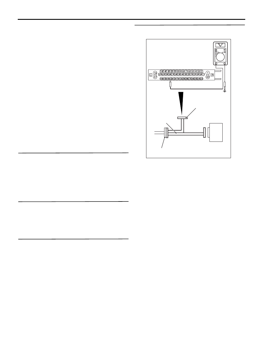
STEP 4. Voltage measurement at the A-58 ASC-
ECU connector

AC606869DE

ASC-ECU

MB991997

Check harness

A-58 ASC-ECU
harness connector

(1) Disconnect the ASC-ECU connector, connect 

special tool ASC check harness (MB991997) to 
the harness-side connector, and then measure 
the voltage at the special tool connector side.
NOTE: Do not connect the special tool to ASC-
ECU.

(2) Turn the ignition switch to the ON position.
(3) Measure the voltage between the rear wheel 

speed sensor <RH> power supply terminal 
(signal terminal) No.43 and the body earth, and 
between the rear wheel speed sensor <RH> 
earth terminal No.42 and the body earth.

OK: 1 V or less

Q: Is the check result normal?

YES : 

Go to Step 5.

NO (Not normal at the terminal No.43 or No.42) : 

Go to Step 6.

TROUBLESHOOTING

ACTIVE STABILITY CONTROL SYSTEM (ASC)

35C-34

STEP 5. Resistance measurement at A-58 ASC-
ECU connector

AC606869DF

ASC-ECU

MB991997

Check harness

A-58 ASC-ECU
harness connector

(1) Disconnect the ASC-ECU connector, connect 

special tool ASC check harness (MB991997) to 
the harness-side connector, and then measure 
the resistance at the special tool connector side.
NOTE: Do not connect the special tool to ASC-
ECU.

(2) Measure the resistance between the rear wheel 

speed sensor <RH> power supply terminal 
(signal terminal) No.43 and the body earth, and 
between the rear wheel speed sensor <RH> 
earth terminal No.42 and the body earth.

OK: No continuity

Q: Is the check result normal?

YES : 

Go to Step 8.

NO (Not normal at the terminal No.43 or No.42) : 

Go to Step 6.

STEP 6. Connector check: A-58 ASC-ECU 
connector, C-67 intermediate connector, D-12 
intermediate connector, F-04 rear wheel speed 
sensor <RH> connector

Q: Is the check result normal?

YES : 

Go to Step 7.

NO : 

Repair the defective connector. Then go to 
Step 13.

STEP 7. Wiring harness check between A-58 
ASC-ECU connector terminal No.43 and F-04 rear 
wheel speed sensor <RH> connector terminal 
No.1, and between A-58 ASC-ECU connector 
terminal No.42 and F-04 rear wheel speed sensor 
<RH> connector terminal No.2.

• Check for short circuit in rear wheel speed sensor 

<RH> circuit

Q: Is the check result normal?

YES : 

Replace the wheel speed sensor <RR> 

(Refer to 

P.35C-188

). Then go to Step 13.

NO : 

Repair the wiring harness. Then go to Step 
13.

STEP 8. Voltage measurement at the A-58 ASC-
ECU connector

AC606870BO

ASC-ECU

MB991997

Check harness

A-58 ASC-ECU
harness connector

(1) Disconnect the ASC-ECU connector, connect 

special tool ASC check harness (MB991997) to 
the ASC-ECU-side connector and harness-side 
connector, and then measure the voltage at the 
special tool connector side.

(2) Turn the ignition switch to the ON position.
(3) Measure the voltage between the rear wheel 

speed sensor <RH> circuit power supply terminal 
(signal terminal) No.43 and the body earth.

OK: Approximately system voltage

Q: Is the check result normal?

YES : 

Go to Step 9.

NO : 

Go to Step 11.

TROUBLESHOOTING

ACTIVE STABILITY CONTROL SYSTEM (ASC)

35C-35

STEP 9. Wiring harness check between A-58 
ASC-ECU connector terminal No.43 and F-04 rear 
wheel speed sensor <RH> connector terminal 
No.1, and between A-58 ASC-ECU connector 
terminal No.42 and F-04 rear wheel speed sensor 
<RH> connector terminal No.2.

• Check for open circuit in rear wheel speed sensor 

<RH> circuit

Q: Is the check result normal?

YES : 

Go to Step 10.

NO : 

Repair the wiring harness. Then go to Step 
13.

STEP 10. Check for wheel speed sensor <RR> as 
a single unit
Refer to 

P.35C-188

.

Q: Is the check result normal?

YES : 

Go to Step 11.

NO : 

Replace the wheel speed sensor <RR> 
(Refer to 

P.35C-188

). Then go to Step 13.

STEP 11. Connector check: A-58 ASC-ECU 
connector, C-67 intermediate connector, D-12 
intermediate connector, F-04 rear wheel speed 
sensor <RH> connector

Q: Is the check result normal?

YES : 

Go to Step 12.

NO : 

Repair the defective connector. Then go to 
Step 13.

STEP 12. Check whether the diagnosis code is 
reset.
(1) Erase the diagnosis code.
(2) Drive the vehicle at 20 km/h or higher.

NOTE: The ABS warning lamp does not turn OFF 
in some cases unless the vehicle runs at 20 km/h 
or higher.

Q: Is the diagnosis code No. C102B set?

YES : 

Replace the hydraulic unit (integrated with 

ASC-ECU) (Refer to 

P.35C-185

). Then go 

to Step 13.

NO : 

Intermittent malfunction (Refer to GROUP 
00 

− How to Use Troubleshooting/How to 

Cope with Intermittent Malfunctions ).

STEP 13. Check whether the diagnosis code is 
reset.
(1) Erase the diagnosis code.
(2) Drive the vehicle at 20 km/h or higher.

NOTE: The ABS warning lamp does not turn OFF 
in some cases unless the vehicle runs at 20 km/h 
or higher.

Q: Is the diagnosis code No. C102B set?

YES : 

Return to Step 1.

NO : 

This diagnosis is complete.

TROUBLESHOOTING

ACTIVE STABILITY CONTROL SYSTEM (ASC)

35C-36

Code No. C1011 Abnormality in FL wheel speed sensor signal

Wheel Speed Sensor Circuit

ASC-ECU

(LH)

(LH)

(RH)

(RH)

FRONT WHEEL SPEED SENSOR

REAR WHEEL SPEED SENSOR

Wire colour code 
B : Black     LG : Light green     G : Green     L : Blue     W : White     Y : Yellow     SB : Sky blue 
BR : Brown     O : Orange     GR : Grey     R : Red     P : Pink     V : Violet     PU : Purple     SI : Silver

ACB02565

AC612690

AP

Connector: A-08 <LHD>

A-08 (B)

AC701238 AE

Connectors: A-08, A-58 <RHD>

A-58 (B)

A-08 (B)


Content   ..  43  44  45  46   ..