Mitsubishi Lancer (4A9 engine). Manual - part 12
PRECAUTIONS BEFORE SERVICE
GENERAL
00-45
ENGINE KEY CODE AND CHASSIS
NUMBER (CHASSIS NO.) REGISTRA-
TION STEPS FOR THE ENGINE-ECU
CAUTION
• Check that diagnosis code No.P0603 "EEP-
ROM fail" is not set. When diagnosis code No.
P0603 "EEPROM fail" is set, the engine-ECU
cannot store engine key code and chassis No.
even if the engine key code and chassis No.
are registered. If this diagnosis code is set,
troubleshoot the engine-ECU and repair, and
then register the engine key code and chassis
No. to the engine-ECU.
•
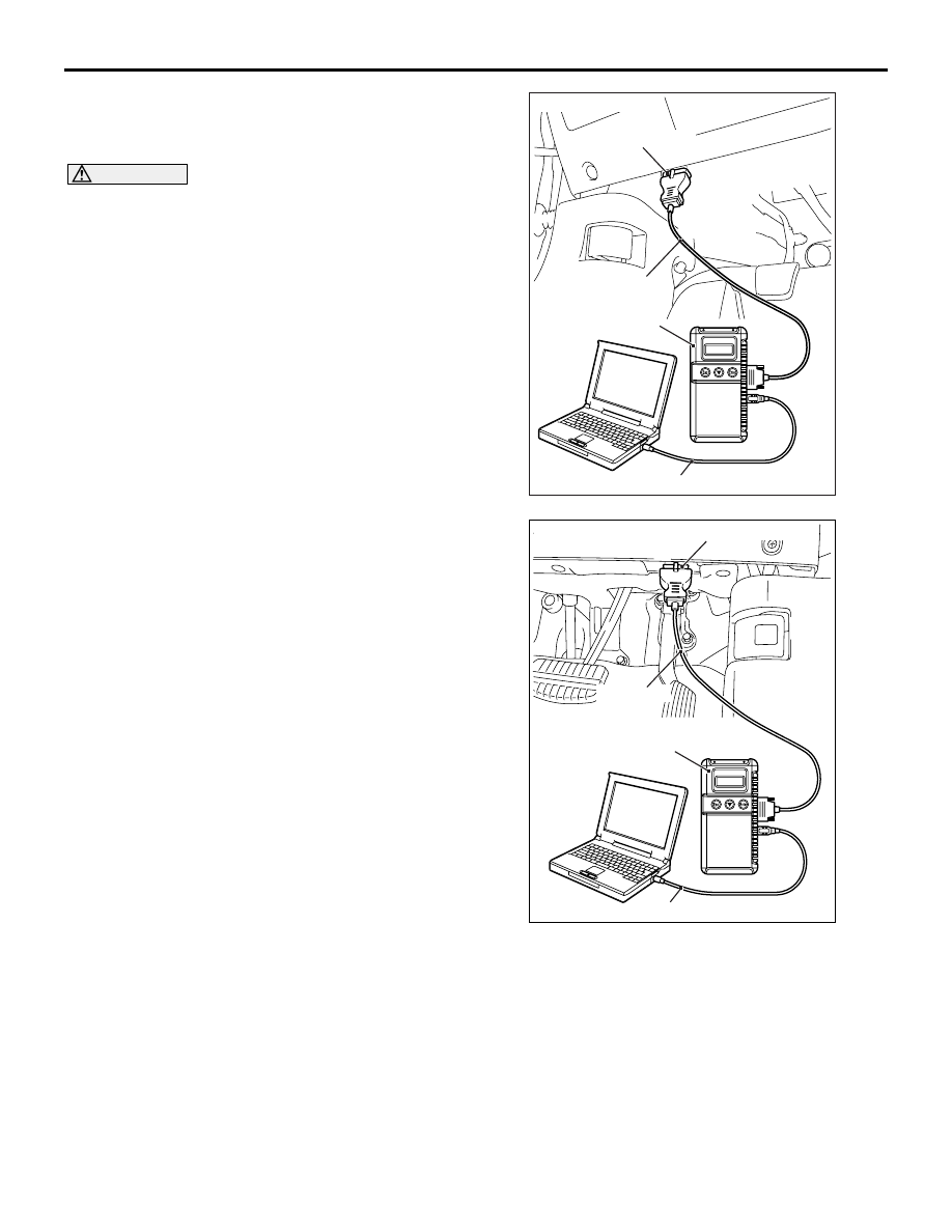
AC608435
MB991827
MB991824
MB991910
AB
Diagnosis connector
<LH drive vehicles>
AC700191
MB991827
MB991824
AB
Diagnosis connector
<RH drive vehicles>
MB991910
Before connecting or disconnecting the
M.U.T.-III, turn the ignition switch to the
"LOCK" (OFF) position.
Connect the M.U.T.-III to the 16-pin diagnosis con-
nector as follows.
NOTE: For details on how to use the M.U.T.-III, refer
to the "M.U.T.-III User's Manual."
1. Ensure that the ignition switch is at the "LOCK"
(OFF) position.
2. Start up the personal computer.
3. Connect special tool USB cable (MB991827) to
special tool V.C.I. (MB991824) and the personal
computer.