Mitsubishi Lancer (4A9 engine). Manual - part 3


  Index      Mitsubishi     Mitsubishi Lancer (4A9 engine) 12GS41 & 44S - service repair manual


Search            


Content   ..  1  2  3  4  ..


Mitsubishi Lancer (4A9 engine). Manual - part 3


HOW TO USE TROUBLESHOOTING/INSPECTION SERVICE POINTS

GENERAL

00-9

NOTE: 

.

For details on how to use the M.U.T.-III, refer to 
the "M.U.T.-III operation manual."

For the vehicles with security alarm sensor, when 
the M.U.T.-III is connected, if the ignition switch is 
turned to the "ON" position and the closed hood 
is opened, the security alarm siren sounds short. 
This short security alarm siren does not indicate 
malfunction. Therefore, ignore it and carry out 
diagnosis using M.U.T.-III.

If the ignition switch is turned to the "ON" position 
with M.U.T.-III connected to the vehicle, head-
lamp automatic levelling warning is displayed on 
the multi-information display in the combination 
meter. This symptom occurs because the head-
lamp automatic levelling-ECU enters the diagno-
sis mode when the M.U.T.-III is connected to the 
diagnosis connector, and it does not indicate mal-
function. Therefore, ignore the indicator display 
and carry out diagnosis using M.U.T.-III. (When 
the M.U.T.-III starts communication with the ECU, 
the indicator display disappears.)

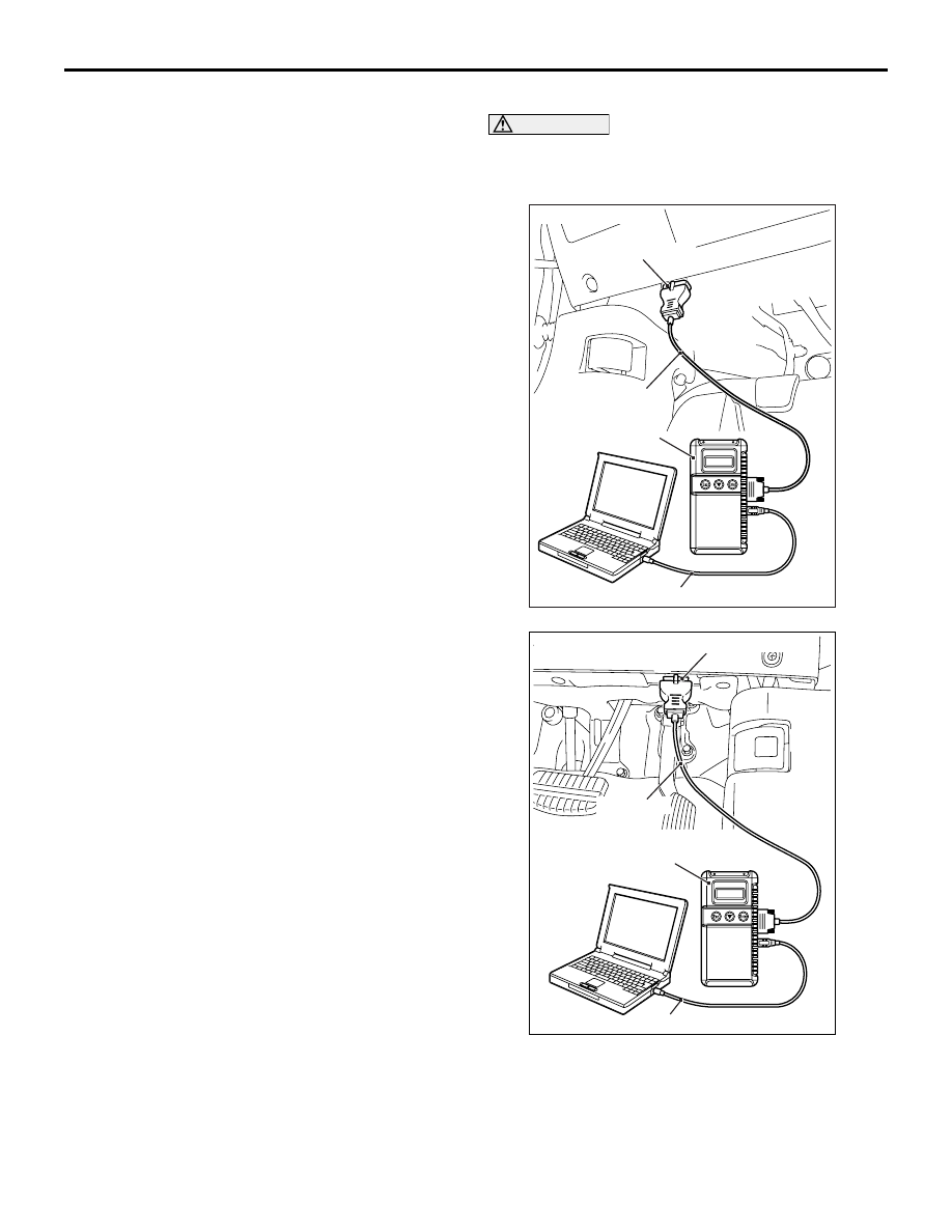
1. Ensure that the ignition switch is at the "LOCK" 

(OFF) position.

2. Start up the personal computer.
3. Connect special tool M.U.T.-III USB cable 

(MB991827) to V.C.I. (MB991824) and the 
personal computer.

4. Connect special tool M.U.T.-III main harness A 

(MB991910) to the V.C.I.

5. Connect the M.U.T.-III main harness A to the 

diagnosis connector of the vehicle.

6. Turn the V.C.I. power switch to the "ON" position.

NOTE: When the V.C.I. is energized, the V.C.I. 
indicator lamp will be illuminated in a green col-
our.

7. Start the M.U.T.-III system on the personal 

computer and turn the ignition switch to the "ON" 
position.

8. Read the diagnosis code.
NOTE: When storing the diagnosis code as refer-
ence information, the freeze frame data obtains the 
data when the diagnosis code is confirmed, and then 
stores the ECU status of that time. By analysing 
each data using M.U.T.-III, troubleshooting can be 
carried out efficiently.
9. Disconnecting the M.U.T.-III is the reverse of the 

connecting sequence, making sure that the 
ignition switch is at the "LOCK" (OFF) position.

ERASING DIAGNOSIS CODE

CAUTION

Before connecting or disconnecting the M.U.T.-
III, turn the ignition switch to the "LOCK" (OFF) 
position.

AC608435

MB991827

MB991824

MB991910

AB

Diagnosis connector

<LH drive vehicles>

AC700191

MB991827

MB991824

AB

Diagnosis connector

<RH drive vehicles>

MB991910

Connect the M.U.T.-III to the diagnosis connector, 
and erase the diagnosis code. The procedure is the 
same as "How to Read Diagnosis Code ."

HOW TO USE TROUBLESHOOTING/INSPECTION SERVICE POINTS

GENERAL

00-10

HOW TO USE THE INSPECTION 
PROCEDURES

M1001013500732

The causes of many of the problems occurring in electric circuitry are generally the connectors, components, 
the ECU, the wiring harnesses between connectors, in that order. These inspection procedures follow this 
order. They first try to discover a problem with a connector or a defective component.

AC301964 AC

 Relevant circuit(s) of the component which
 the Code No. indicates are described.

Grey

AC701738AB

Explains about the basic 
operation of the components.

Explains about 
technical details.

Describes the 
conditions for that 
diagnosis code being
set.

Start of diagnosis
procedure

Describes possible
causes(s) for that 
diagnosis code.

Describes 
inspection
procedure.

HOW TO USE TROUBLESHOOTING/INSPECTION SERVICE POINTS

GENERAL

00-11

CURRENT TROUBLE

Indicates that the status is "Active" and the trouble is 
currently present. Carry out troubleshooting as 
described in the applicable inspection procedure.

PAST TROUBLE

Indicates that the status is "Stored" and the trouble is 
historic. Since the trouble may still be present, set 
the vehicle to the diagnosis code detection condition 
and check that the status changes to "Active". If the 
status does not change from "Stored", observe the 
applicable inspection procedure with particular 
emphasis on connector(s) and wiring harness.

HARNESS CHECK

Check for an open or short circuit in the harness 
between the terminals which are faulty according to 
the connector measurements. Carry out this inspec-
tion while referring to the Electrical Wiring Manual. 
Here, "Check the wiring harness between the power 
supply and terminal xx" also includes checking for 
blown fuse. For inspection service points when there 
is a blown fuse, refer to "Inspection Service Points 
for a Blown Fus

P.00-14

."

MEASURES TO TAKE AFTER REPLAC-
ING THE ECU

If the trouble symptoms have not disappeared even 
after replacing the ECU, repeat the inspection proce-
dure from the beginning.

HOW TO USE TROUBLESHOOTING/INSPECTION SERVICE POINTS

GENERAL

00-12

CONNECTOR MEASUREMENT SERVICE 
POINTS

M1001013600632

CAUTION

During diagnosis, a diagnosis code associated 
with other system may be set when the ignition 
switch is turned on with connector(s) discon-
nected. On completion, confirm all systems for 
diagnosis code(s). If diagnosis code(s) are set, 
erase them all.
Turn the ignition switch to the "LOCK" (OFF) position 
when connecting and disconnecting the connectors. 
Turn the ignition switch to "ON" when measuring, 
unless there are instructions to the contrary.
IF INSPECTING WITH THE CONNECTOR 
CONNECTED <WATERPROOF CONNECTORS>

CAUTION

Never insert a test probe from the harness side, 
as this will reduce the waterproof performance 
and result in corrosion.

AC105597AB

Special tool

Use the special tools such as test harness, harness 
connector or check harness.

IF INSPECTING WITH THE CONNECTOR 
CONNECTED <ORDINARY (NON-WATERPROOF) 
CONNECTORS>

AC105598AH

MB992006

Inspect by inserting a test probe from the harness 
side. If the connector is too small to insert a test 
probe (e.g. control unit connector), do not insert it 
forcibly. Use special tool extra fine probe 
(MB992006).

IF INSPECTING WITH THE CONNECTOR 
DISCONNECTED <WHEN INSPECTING A 
FEMALE PIN>

CAUTION

• Use special tool inspection harness 

(MB991219). If the test bar is inserted forcibly, 
it will cause a poor contact. 

AC105599

MB991219

AB

If the connector is disconnected, a diagnosis 
code may be stored for the system to be 
checked or other systems.

Use inspection harness (MB991219) of special tool 
harness set (MB991223).

IF INSPECTING WITH THE CONNECTOR 
DISCONNECTED <WHEN INSPECTING A MALE 
PIN>

CAUTION

• Be careful not to short the connector pins 

with the test bars. To do so may damage the 
circuits inside the ECU.

AC105600

If the connector is disconnected, a diagnosis 
code may be stored for the system to be 
checked or other systems.

Touch the pin directly with the test bar.


Content   ..  1  2  3  4  ..