Mitsubishi Evolution X. Manual - part 989


  Index      Mitsubishi     Mitsubishi Evolution X - service repair manual 2008 year


Search            


Content   ..  987  988  989  990   ..


Mitsubishi Evolution X. Manual - part 989


RADIO AND CD PLAYER

TSB Revision

CHASSIS ELECTRICAL

54A-317

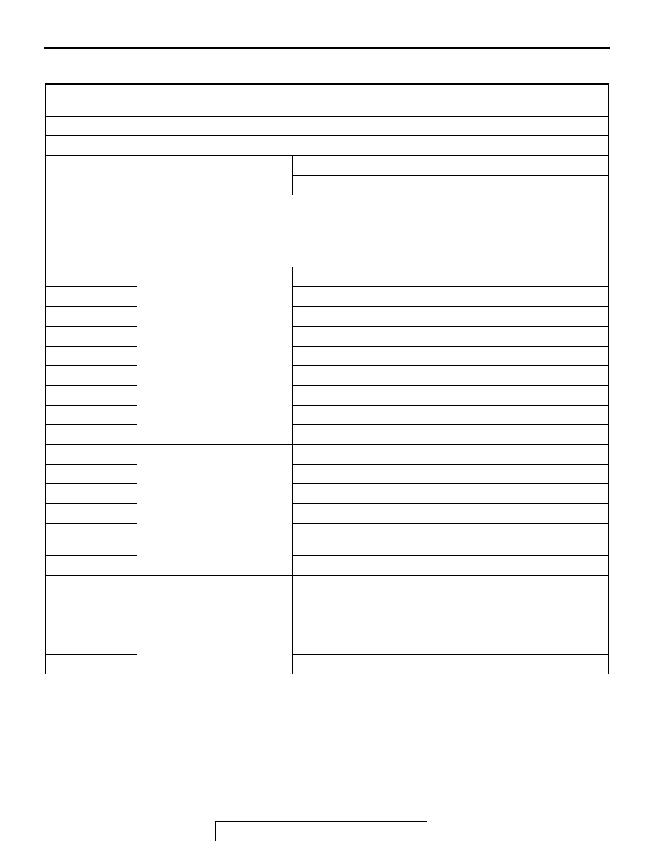
TROUBLE SYMPTOM CHART

M1544004901302

Inspection 
Procedure No.

Trouble symptom

Reference 
page

1

Power is not turned ON when the power switch is turned ON.

P.54A-318

2

No sound is heard. <Vehicles with audio amplifier>

P.54A-322

3

No sound is heard from one 
of the speakers.

<Vehicles without audio amplifier>

P.54A-328

<Vehicles with audio amplifier>

P.54A-333

4

The audio does not operate normally by operating the radio and CD player of 
the center panel unit.

P.54A-340

5

Audio illuminations does not work normally.

P.54A-344

6

The sound of external input are not played.

P.54A-348

7

Noise

Noise is present while moving (AM).

P.54A-350

8

Noise is present while moving (FM).

P.54A-350

9

Sound mixed with noise, only at night (AM).

P.54A-351

10

Noise is overpowering both AM and FM.

P.54A-352

11

Excessive noise on AM and FM.

P.54A-352

12

Noise is detected with engine running.

P.54A-353

13

Noise appears during vibration or shocks.

P.54A-354

14

Noise is present while moving (FM).

P.54A-355

15

Constant noise.

P.54A-356

16

Radio

No reception (AM).

P.54A-356

17

Poor reception.

P.54A-357

18

Distortion on AM and/or FM.

P.54A-358

19

Distortion on FM only.

P.54A-359

20

Auto select function inoperative, too few 
automatic stations are selected.

P.54A-359

21

Preset stations are erased.

P.54A-360

22

CD player

CD cannot be inserted.

P.54A-360

23

No sound. (CD only).

P.54A-361

24

CD sound skips.

P.54A-361

25

Sound quality is poor.

P.54A-362

26

CD cannot be ejected.

P.54A-362

RADIO AND CD PLAYER

TSB Revision

CHASSIS ELECTRICAL

54A-318

SYMPTOM PROCEDURES

Inspection Procedure 1: Power is not turned ON when the power switch is turned ON.

CAUTION

When replacing the ECU, always check that the 
communication circuit is normal.

.

Radio and CD Player Power Supply Circuit

ETACS-
ECU

RELAY BOX
 ENGINE 
 COMPARTMENT

CAN
COMMUNICATION LINE

ETACS-ECU

RADIO AND CD PLAYER

INPUT SIGNAL

IGNITION SWITCH (ACC)

FUSIBLE
LINK

36

AC708951BD

Connector: C-107

AC708972BA

Connectors: C-307, C-317

ETACS-ECU

C-307 (B)

C-317

RADIO AND CD PLAYER

TSB Revision

CHASSIS ELECTRICAL

54A-319

OPERATION

When the ignition switch is in the ON or ACC posi-
tion, the radio and CD player power can be turned 
ON. With the radio and CD player power ON, when 
the ignition switch is turned to the OFF position, the 
power for radio and CD player is also turned OFF.

.

COMMENTS ON TROUBLE SYMPTOM

Provided that the audio diagnostic trouble code is not 
set, if the power for radio and CD player cannot be 
turned ON, the radio and CD player, or power supply 
circuit for radio and CD player may have a problem, 
or the option coding information may be inconsistent.

.

PROBABLE CAUSES

• The radio and CD player may be defective

• The ETACS-ECU may be defective

• Option coding information inconsistency

• Damaged harness wires and connectors

DIAGNOSIS

Required Special Tools:

• MB991223: Harness Set

• MB992006: Extra Fine Probe

• MB991958: Scan Tool (M.U.T.-III Sub Assembly)

• MB991824: Vehicle Communication Interface (V.C.I.)

• MB991827: M.U.T.-III USB Cable

• MB991910: M.U.T.-III Main Harness A

STEP 1. ETACS-ECU coding data check.
(1) Operate scan tool MB991958 to read the ETACS-ECU 

option coding information (Refer to GROUP 00, Coding 
Table 

P.00-39

).

(2) Check that the "AUDIO" is set to "enabled."
Q: Is the check result normal?

YES : Go to Step 2.
NO :  Operate scan tool MB991958 to set the option coding 

"AUDIO" to "enabled," and check the trouble 
symptom.

AC608435

Data link connector

MB991827

MB991824

MB991910

AB

RADIO AND CD PLAYER

TSB Revision

CHASSIS ELECTRICAL

54A-320

STEP 2. Using scan tool MB991958, diagnose the CAN bus 
line.
Use scan tool MB991958 to diagnose the CAN bus lines.

CAUTION

To prevent damage to scan tool MB991958, always turn the 
ignition switch to the "LOCK" (OFF) position before con-
necting or disconnecting scan tool MB991958.
(1) Connect scan tool MB991958 to the data link connector.
(2) Turn the ignition switch to "ON" position.
(3) Diagnose the CAN bus line.
Q: Is the check result normal?

YES : Go to Step 3.
NO :  Repair the CAN bus line. (Refer to GROUP 54C, 

Diagnosis 

P.54C-14

.) On completion, go to Step 3.

STEP 3. Using scan tool MB991958, read the ETACS-ECU 
diagnostic trouble code. 
Check if the diagnostic trouble code is set to the ETACS-ECU.
Q: Is the DTC set?

YES : Troubleshoot the ETACS-ECU (Refer to GROUP 

54A, ETACS, Diagnosis 

P.54A-582

).

NO :  Go to Step 4.

STEP 4. Using scan tool MB991958, check data list.
Check the input signal of ACC relay.

• Turn the ignition switch to the ACC position.

OK: Normal condition is displayed.

Q: Is the check result normal?

YES : Go to Step 5.
NO :  Refer to GROUP 54A, ETACS, Diagnosis 

− Inspection 

Procedure 1 "The ignition switch (ACC) signal is not 
received" 

P.54A-640

.

STEP 5. Check ETACS-ECU connector C-317 and radio and 
CD player connector C-107 for loose, corroded or 
damaged terminals, or terminals pushed back in the 
connector.
Q: Are ETACS-ECU connector C-317 and radio and CD 

player connector C-107 in good condition?
YES : 
Go to Step 6.
NO :  Repair or replace the damaged component(s) (Refer 

to GROUP 00E, Harness Connector Inspection 

P.00E-2

). The steering remote control switch should 

work normally.

Item No.

Item name

Normal conditions

Item 288

ACC switch

ON


Content   ..  987  988  989  990   ..