Mitsubishi Evolution X. Manual - part 988


  Index      Mitsubishi     Mitsubishi Evolution X - service repair manual 2008 year


Search            


Content   ..  986  987  988  989   ..


Mitsubishi Evolution X. Manual - part 988


RADIO AND CD PLAYER

TSB Revision

CHASSIS ELECTRICAL

54A-313

STEP 2. Check center panel unit connector C-124 and 
radio and CD player connector C-109 for loose, corroded 
or damaged terminals, or terminals pushed back in the 
connector.
Q: Are center panel unit connector C-124 and radio and CD 

player connector C-109 in good condition?
YES : 
Go to Step 3.
NO :  Repair or replace the damaged component(s) (Refer 

to GROUP 00E, Harness Connector Inspection 

P.00E-2

).

STEP 3. Check the wiring harness between center panel 
unit connector C-124 (terminal 1, 2) and radio and CD 
player connector C-109 (terminal 8, 18).
Q: Is the wiring harness between center panel unit 

connector C-124 (terminal 1, 2) and radio and CD player 
connector C-109 (terminal 8, 18) in good condition?
YES : 
Go to Step 4.
NO :  The wiring harness may be damaged or the 

connector(s) may have loose, corroded or damaged 
terminals, or terminals pushed back in the connector. 
Repair the wiring harness as necessary.

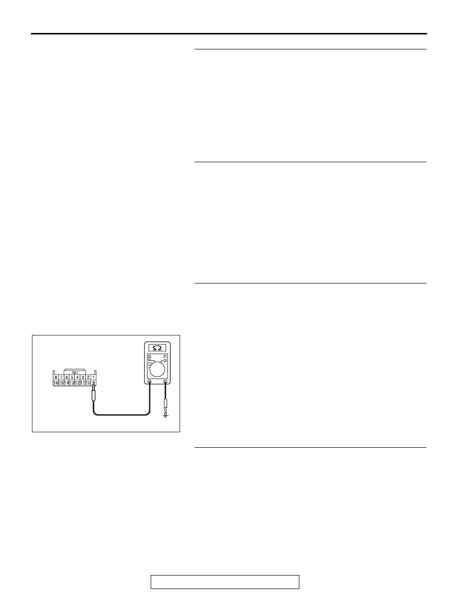
STEP 4. Check the ground circuit to the center panel unit. 
Measure the resistance at center panel unit connector 
C-124.
(1) Disconnect the connector, and measure at the wiring 

harness side.

(2) Measure resistance between terminal 9 and ground.

OK: The resistance should be 2 ohm or less.

Q: Is the measured resistance 2 ohms or less?

YES : Go to Step 6.
NO :  Go to Step 5.

STEP 5. Check the wiring harness between center panel 
unit connector C-124 (terminal 9) and ground.

• Check the ground wires for open circuit.

Q: Is the wiring harness between center panel unit 

connector C-124 (terminal 9) and ground in good 
condition?
YES : 
Go to Step 8.
NO :  The wiring harness may be damaged or the 

connector(s) may have loose, corroded or damaged 
terminals, or terminals pushed back in the connector. 
Repair the wiring harness as necessary.

AC709322 AW

Harness side: C-124

RADIO AND CD PLAYER

TSB Revision

CHASSIS ELECTRICAL

54A-314

STEP 6. Check the power supply circuit to the center panel 
unit. Measure the voltage at center panel unit connector 
C-124.
(1) Disconnect the connector, and measure at the harness side 

connector.

(2) Measure voltage between terminal 7 and ground.

OK: Battery voltage

Q: Is the measured voltage battery voltage?

YES : Go to Step 8.
NO :  Go to Step 7.

STEP 7. Check the wiring harness between center panel 
unit connector C-124 (terminal 7) and fusible link 34.

• Check the power supply line for open circuit and short cir-

cuit.

NOTE: Also ETACS-ECU connector C-307, C-317 for loose, 
corroded, or damaged terminals, or terminals pushed back in 
the connector. If joint connector ETACS-ECU connector C-307, 
C-317 are damaged, repair or replace the connector as 
described in GROUP 00E, Harness Connector Inspection 

P.00E-2

.

Q: Is the wiring harness between center panel unit 

connector C-124 (terminal 7) and fusible link 34 in good 
condition?
YES : 
Go to Step 8.
NO :  The wiring harness may be damaged or the 

connector(s) may have loose, corroded or damaged 
terminals, or terminals pushed back in the connector. 
Repair the wiring harness as necessary.

STEP 8. Recheck for diagnostic trouble code.
Check again if the DTC is set to the radio and CD player.
(1) Erase the DTC.
(2) Turn the ignition switch from "LOCK" (OFF) position to "ON" 

position.

(3) Check if the DTC is set.
Q: Is the DTC set?

YES : Go to Step 9.
NO :  The trouble can be an intermittent malfunction (Refer 

to GROUP 00, How to use 
Troubleshooting/inspection Service Points, How to 
Cope with Intermittent Malfunction 

P.00-15

).

AC709325 AH

Harness side: C-124

RADIO AND CD PLAYER

TSB Revision

CHASSIS ELECTRICAL

54A-315

STEP 9. Recheck for diagnostic trouble code.
Temporarily replace the center panel unit, and recheck that the 
DTC is set to the radio and CD player.
(1) Erase the DTC.
(2) Turn the ignition switch from "LOCK" (OFF) position to "ON" 

position.

(3) Check if the DTC is set.
Q: Is the DTC set?

YES : Replace the radio and CD player.
NO :  Replace the center panel unit.

DTC B2451: Audio panel type error

CAUTION

If there is any problem in the CAN bus lines, an 
incorrect diagnostic trouble code may be set. 
Prior to this diagnosis, always diagnose the CAN 
bus lines.

.

TROUBLE JUDGMENT

If the radio and CD player consecutively receive the 
display trouble signal from the center panel assem-
bly for 1 minute, the diagnostic trouble code is set.

.

COMMENTS ON TROUBLE SYMPTOM

The center panel assembly or CAN bus line may 
have a problem.

.

PROBABLE CAUSES

• The CAN bus line may be defective.

• The radio and CD player may be defective.

DIAGNOSIS

Required Special Tools:

• MB991958: Scan Tool (M.U.T.-III Sub Assembly)

• MB991824: Vehicle Communication Interface (V.C.I.)

• MB991827: M.U.T.-III USB Cable

• MB991910: M.U.T.-III Main Harness A

RADIO AND CD PLAYER

TSB Revision

CHASSIS ELECTRICAL

54A-316

STEP 1. Using scan tool MB991958, diagnose the CAN bus 
line.
Use scan tool MB991958 to diagnose the CAN bus lines.

CAUTION

To prevent damage to scan tool MB991958, always turn the 
ignition switch to the "LOCK" (OFF) position before con-
necting or disconnecting scan tool MB991958.
(1) Connect scan tool MB991958. Refer to "How to connect the 

Scan Tool (M.U.T.-III) 

P.54A-285

."

(2) Turn the ignition switch to "ON" position.
(3) Diagnose the CAN bus line.
Q: Is the check result normal?

YES : Go to Step 2.
NO :  Repair the CAN bus line (Refer to GROUP 54C, 

Diagnosis 

P.54C-14

).

STEP 2. Recheck for diagnostic trouble code.
Check again if the DTC is set to the radio and CD player.
(1) Erase the DTC.
(2) Turn the ignition switch from "LOCK" (OFF) position to "ON" 

position.

(3) Check if the DTC is set.
Q: Is the DTC set?

YES : Replace the radio and CD player.
NO :  The trouble can be an intermittent malfunction (Refer 

to GROUP 00, How to use 
Troubleshooting/inspection Service Points, How to 
Cope with Intermittent Malfunction 

P.00-15

).

AC608435

Data link connector

MB991827

MB991824

MB991910

AB


Content   ..  986  987  988  989   ..