Mitsubishi Evolution X. Manual - part 959


  Index      Mitsubishi     Mitsubishi Evolution X - service repair manual 2008 year


Search            


Content   ..  957  958  959  960   ..


Mitsubishi Evolution X. Manual - part 959


REAR COMBINATION LIGHT

TSB Revision

CHASSIS ELECTRICAL

54A-197

DIAGNOSTIC TROUBLE CODE PROCEDURES

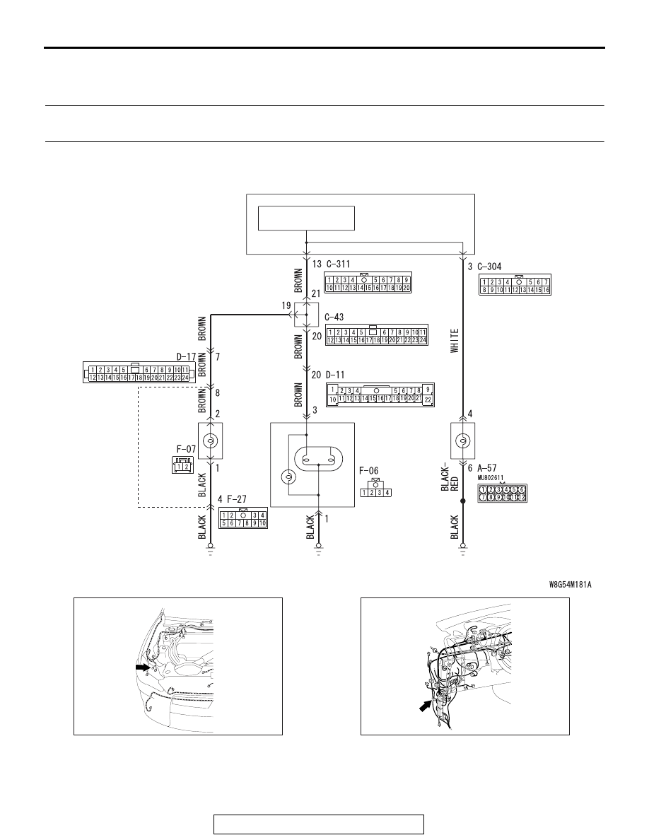
DTC B16A0: Taillight (RH) circuit open (Open circuit in taillight (RH) or position light (RH))


DTC B16A7: Taillight (RH) circuit short (Short circuit in taillight (RH) or position light (RH))

ETACS-ECU

JOINT CONNECTOR

TAILLIGHT 
CONTROL CIRCUIT

Taillight and Position Light Circuit

REAR
COMBINATION
LIGHT  
(TAILLIGHT: RH)

TAILLIGHT 
(RH)

HEADLIGHT
ASSEMBLY
(POSITION
 LIGHT: RH)

AC708948AH

Connector: A-57

A-57 (B)

AC708950

Connector: C-43

BG

C-43 (B)

REAR COMBINATION LIGHT

TSB Revision

CHASSIS ELECTRICAL

54A-198

.

TROUBLE JUDGMENT

When an open circuit is detected in the taillight or 
position light circuit, the ETACS-ECU sets DTC 
B16A0. If a short circuit is detected, DTC B16A7 is 
set.

.

TECHNICAL DESCRIPTION (COMMENT)

The problem detection of taillight or position light is 
made based on the digital feed back signal (input 
signal to ETACS-ECU) which operates the taillight or 
position light. When the ignition switch is "ON", the 
ETACS-ECU determines the taillight or position light 
circuit state from the load placed on the line. After 
100 ms has elapsed since the start of the check, the 
ETACS-ECU performs a sampling with each 10 ms. 
If an abnormality is detected, it increases the counter 
by 2, and when no abnormality is detected, it 
decreases the counter by 1. Once the counter 
reaches "10", the ETACS-ECU sets the DTC B16A0 
if the load is detected on the line, and sets the DTC 
B16A7 if no load is detected.

.

TROUBLESHOOTING HINTS

• The wiring harness or connectors may have 

loose, corroded, or damaged terminals, or termi-
nals pushed back in the connector

• Malfunction of bulbs

• Malfunction of the ETACS-ECU

DIAGNOSIS

Required Special Tools:

• MB992006: Extra fine probe

• MB991223: Harness set

• MB991958 Scan Tool (M.U.T.-III Sub Assembly)

• MB991824: Vehicle Communication Interface (V.C.I.)

• MB991827 M.U.T.-III USB Cable

• MB991910 M.U.T.-III Main Harness A (Vehicles with 

CAN communication system)

STEP 1. Bulb check.
Check the bulb(s) of the light that does not illuminate.
Q: Is the check result normal?

YES : Go to Step 2.
NO :  Replace the bulb(s) of the light that does not 

illuminate.

AC708972

Connectors: C-304, C-311

AW

C-311

C-304

AC708955AU

Connectors: D-11, D-17

D-17 (BR)

D-11

AC708970AN

Connectors: F-06, F-07, F-27

F-27

F-06

F-07 (GR)

REAR COMBINATION LIGHT

TSB Revision

CHASSIS ELECTRICAL

54A-199

STEP 2. Check headlight assembly (RH) connector A-57, 
rear combination light (RH) connector F-06 and taillight 
(RH) connector F-07 for loose, corroded or damaged 
terminals, or terminals pushed back in the connector.
Q: Is headlight assembly (RH) connector A-57, rear 

combination light (RH) connector F-06 and taillight (RH) 
connector F-07 in good condition?
YES : 
Go to Step 3.
NO  :  Repair or replace the damaged component(s). Refer 

to GROUP 00E, Harness Connector Inspection 

P.00E-2

.

STEP 3. Resistance measurement at headlight assembly 
(RH) connector A-57, rear combination light (RH) 
connector F-06 and taillight (RH) connector F-07.
(1) Disconnect the connector, and measure at the wiring 

harness side.

(2) Measure the resistance between the connector of light 

which does not illuminate and the body ground.

Measure the resistance between headlight assembly 
(RH) connector A-57 (terminal 6) and the body ground.

Measure the resistance between rear combination light 
(RH) connector F-06 (terminal 1) and the body ground.

Measure the resistance between taillight (RH) connector 
F-07 (terminal 1) and the body ground.

OK: The measured value should be continuity 
exists (2 

 or less).

Q: Does the measured resistance value correspond with 

this range?
YES : 
Go to Step 5.
NO :  Go to Step 4.

AC709322 AG

Harness side: A-57

AC608255 AW

Harness side: F-06

AC709322 AP

Harness side: F-07

REAR COMBINATION LIGHT

TSB Revision

CHASSIS ELECTRICAL

54A-200

STEP 4. Check the wiring harness between headlight 
assembly connector, rear combination light connector or 
tail light connector and the body ground.
Check the ground line for open circuit.

• Check the wiring harness between headlight assembly (RH) 

connector A-57 (terminal 6) and the body ground.

• Check the wiring harness between rear combination light 

(RH) connector F-06 (terminal 1) and the body ground.

• Check the wiring harness between taillight (RH) connector 

F-07 (terminal 1) and the body ground.
NOTE: Also check intermediate connector F-27 for loose, 
corroded, or damaged terminals, or terminals pushed back 
in the connector. If intermediate connector F-27 is dam-
aged, repair or replace the connector as described in 
GROUP 00E, Harness Connector Inspection 

P.00E-2

.

Q: Is the wiring harness between headlight assembly 

connector, rear combination light connector or tail light 
connector and the body ground in good condition?
YES : 
Go to Step 7.
NO :  The wiring harness may be damaged or the 

connector(s) may have loose, corroded or damaged 
terminals, or terminals pushed back in the connector. 
Repair the wiring harness as necessary.

STEP 5. Check ETACS-ECU connectors C-304 <position 
light> and C-311 <taillight> for loose, corroded or damaged 
terminals, or terminals pushed back in the connector.
Q: Is ETACS-ECU connectors C-304 <position light> and 

C-311 <taillight> in good condition?
YES : 
Go to Step 6.
NO :  Repair or replace the damaged component(s). Refer 

to GROUP 00E, Harness Connector Inspection 

P.00E-2

.


Content   ..  957  958  959  960   ..