Mitsubishi Evolution X. Manual - part 948


  Index      Mitsubishi     Mitsubishi Evolution X - service repair manual 2008 year


Search            


Content   ..  946  947  948  949   ..


Mitsubishi Evolution X. Manual - part 948


HEADLIGHT

TSB Revision

CHASSIS ELECTRICAL

54A-153

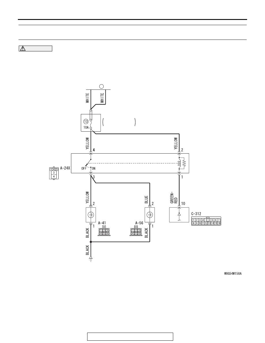
Inspection Procedure 8: Daytime running light function does not work normally. <Discharge type 
headlight>

CAUTION

Whenever the ECU is replaced, ensure that the 
input and output signal circuits are normal.

Daytime Running Light Circuit

FUSIBLE
LINK

36

DAYTIME 
RUNNING 
LIGHT RELAY

           HEADLIGHT
           ASSENMBLY
(DRL: LH)          (DRL: RH)

RELAY BOX

ENGINE 
COMPARTMENT

ETACS-ECU

HEADLIGHT

TSB Revision

CHASSIS ELECTRICAL

54A-154

.

COMMENTS ON TROUBLE SYMPTOM

If the daytime running lights do not illuminate, the 
wiring harness connector(s), the bulb or the 
ETACS-ECU may have a problem.

.

PROBABLE CAUSES

• Burned-out daytime running light bulb

• Malfunction of the daytime running light relay

• Malfunction of the ETACS-ECU

• Damaged harness wires and connectors

DIAGNOSIS

Required Special Tools:

• MB991223: Harness Set

• MB992006: Extra Fine Probe

• MB991958: Scan Tool (M.U.T.-III Sub Assembly)

• MB991824: V.C.I.

• MB991827: M.U.T.-III USB Cable

• MB991910: M.U.T.-III Main Harness A

STEP 1. Check that the tail/stop lights and headlights 
operate.
Check that the tail/stop lights and headlights illuminate nor-
mally.
Q: Do the tail/stop lights and headlights operate normally?

YES : Go to Step 2.
NO :  Check the tail/stop lights and the headlights (Refer to 

trouble symptom chart 

P.54A-127

).

AC709111

Connector: A-24X

AF

AC708949AI

Connector: A-41

A-41 (B)

AC708948AK

Connector: A-56

A-56 (B)

AC708972AP

Connector: C-312

ETACS-ECU

HEADLIGHT

TSB Revision

CHASSIS ELECTRICAL

54A-155

STEP 2. Check the daytime running light bulb.
(1) Remove the daytime running light bulb.
(2) Verify that the daytime running light bulb is not damaged or 

burned out.

Q: Is the daytime running light bulb in good condition?

YES : Go to Step 3.
NO :  Replace the fog light bulb. Verify that the daytime 

running lights illuminate normally.

STEP 3. Using scan tool MB991958, diagnose the CAN bus 
line.

CAUTION

To prevent damage to scan tool MB991958, always turn the 
ignition switch to the "LOCK" (OFF) position before con-
necting or disconnecting scan tool MB991958.
(1) Connect scan tool MB991958. Refer to "How to connect 

scan tool (M.U.T.-III) 

P.54A-105

."

(2) Turn the ignition switch to the "ON" position.
(3) Diagnose the CAN bus line.
(4) Turn the ignition switch to the "LOCK" (OFF) position.
Q: Is the CAN bus line found to be normal?

YES : Go to Step 4.
NO :  Repair the CAN bus line (Refer to GROUP 54C, 

Diagnosis 

P.54C-14

).

STEP 4. Using scan tool MB991958, read the ETACS-ECU 
diagnostic trouble code.
Check whether ETACS-ECU DTCs are set.
(1) Turn the ignition switch to the "ON" position.
(2) Check for ETACS-ECU DTCs.
(3) Turn the ignition switch to the "LOCK" (OFF) position.
Q: Is the DTC set?

YES : Diagnose the ETACS-ECU. Refer to ETACS, 

Diagnosis 

P.54A-582

.

NO :  Go to Step 5.

AC608435

Data link connector

MB991827

MB991824

MB991910

AB

HEADLIGHT

TSB Revision

CHASSIS ELECTRICAL

54A-156

STEP 5. Using scan tool MB991958, read the MFI system 
diagnostic trouble code.
Check whether engine control module DTCs are set or not.
(1) Turn the ignition switch to the "ON" position.
(2) Check for engine control module DTCs.
(3) Turn the ignition switch to the "LOCK" (OFF) position.
Q: Is the DTC set?

YES : Diagnose the MFI system. Refer to GROUP 13A, 

Diagnosis 

P.13A-44

.

NO :  Go to Step 6.

STEP 6. Check the parking brake switch.
Check the input signals from the parking brake switch.
(1) Turn the ignition switch to the "ON" position.
(2) Check that the brake warning light on the combination 

meter goes off when the parking brake lever is released.

(3) Turn the ignition switch to the "LOCK" (OFF) position.
Q: Does the brake warning light go off?

YES : Go to Step 7.
NO :  Refer to GROUP 36, Diagnosis, Inspection Procedure 

P.36-7

. Verify that the daytime running light function 

does not work normally.

STEP 7. Check daytime running light (LH) connector A-41, 
daytime running light (RH) A-56 for loose, corroded or 
damaged terminals, or terminals pushed back in the 
connector.
Q: Is daytime running light (LH) connector A-41, daytime 

running light (RH) A-56 in good condition?
YES : 
Go to Step 8.
NO :  Repair the damaged parts.

STEP 8. Check the ground circuit to the daytime running 
light (LH) or daytime running light (RH). Measure the 
resistance at daytime running light (LH) connector A-41 or 
daytime running light (RH) connector A-56.
(1) Disconnect the connector, and measure at the wiring 

harness side.

(2) Check the resistance between the fog light connector and 

ground.

• Resistance between A-41 daytime running light (LH) 

connector terminal No.1 and ground

• Resistance between A-56 daytime running light (RH) 

connector terminal No.1 and ground

OK: The resistance should be 2 ohm or less.

Q: Is the measured resistance 2 ohms or less?

YES : Go to Step 10.
NO :  Go to Step 9.

AC702818 CZ

Connectors A-41, A-56 
(Harness side)


Content   ..  946  947  948  949   ..