Mitsubishi Evolution X. Manual - part 939
HEADLIGHT
TSB Revision
CHASSIS ELECTRICAL
54A-117
.
DIAGNOSTIC FUNCTION
When the right bulb of turn-signal light is blown, the
ETACS-ECU sets DTC B16A4.
.
TECHNICAL DESCRIPTION (COMMENT)
The ETACS-ECU sets DTC B16A4 under the follow-
ing conditions.
• If there is a malfunction to the right turn-signal
light bulb, the blown right bulb counter counts
once when the illumination of hazard or turn-sig-
nal light (right side) is attempted.
• If the blown right bulb counter reaches "3," the
DTC B16A4 is set.
.
TROUBLESHOOTING HINTS
• Malfunction of turn-signal light bulb (right side)
• Malfunction of the ETACS-ECU
• The wiring harness or connectors may have
loose, corroded, or damaged terminals, or termi-
nals pushed back in the connector
DIAGNOSIS
Required Special Tools:
• MB991958: Scan Tool (M.U.T.-III Sub Assembly)
• MB991824: Vehicle Communication Interface (V.C.I.)
• MB991827: M.U.T.-III USB Cable
• MB991910: M.U.T.-III Main Harness A (Vehicles with
CAN communication system)
STEP 1. Bulb check.
Check whether the bulb of turn-signal light which does not illu-
minate is normal.
Q: Is the check result normal?
YES : Go to Step 2.
NO : Replace the bulb of turn-signal light which does not
illuminate.
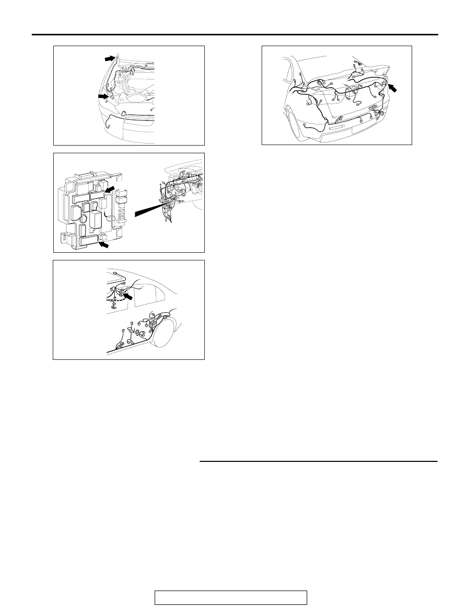
AC708948
A-02 (B)
AG
Connectors: A-02, A-57
A-57 (B)
AC708972
Connectors: C-304, C-311
AW
C-311
C-304
AC708955
Connector: D-11
AO
AC708970AI
Connector: F-06