Mitsubishi Evolution X. Manual - part 937
HEADLIGHT
TSB Revision
CHASSIS ELECTRICAL
54A-109
STEP 2. Check headlight assembly (LH) connector A-40
<front>, side turn-signal light (LH) connector A-12 <side>,
rear combination light (LH) connector F-25 <rear> for
loose, corroded or damaged terminals, or terminals
pushed back in the connector.
Q: Are headlight assembly (LH) connector A-40 <front>,
side turn-signal light (LH) connector A-12 <side>, rear
combination light (LH) connector F-25 <rear> in good
condition?
YES : Go to Step 3.
NO : Repair or replace the damaged component(s). Refer
to GROUP 00E, Harness Connector Inspection
STEP 3. Resistance measurement at headlight assembly
(LH) connector A-40 <front>, side turn-signal light (LH)
connector A-12 <side>, and rear combination light (LH)
connector F-25 <rear>.
(1) Disconnect the connector, and measure at the wiring
harness side.
(2) Measure the resistance between the connector terminal of
light which does not illuminate and ground.
•
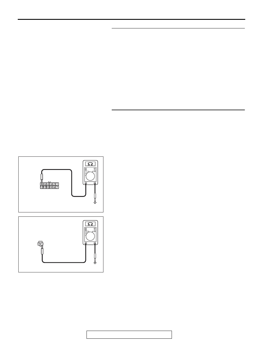
Measure the resistance between the headlight assem-
bly (LH) connector A-40 (terminal 6) and body ground.
<Front>
•
Measure the resistance between side turn-signal light
(LH) connector A-12 (terminal 1) and body ground.
<Side>
AC709322 AD
Harness side: A-40
AC709322 AE
Harness side: A-12