Mitsubishi Evolution X. Manual - part 904


  Index      Mitsubishi     Mitsubishi Evolution X - service repair manual 2008 year


Search            


Content   ..  902  903  904  905   ..


Mitsubishi Evolution X. Manual - part 904


TRAILING ARM

TSB Revision

REAR SUSPENSION

34-17

TRAILING ARM

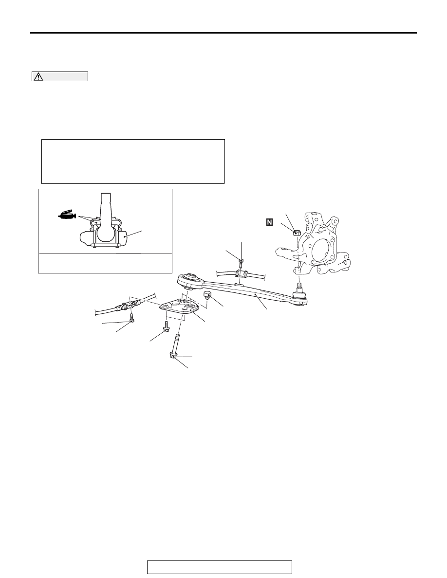
REMOVAL AND INSTALLATION

M1341002200981

CAUTION

• Do not damage the trailing arm ball joint dust cover during maintenance. If it is damaged, replace 

the trailing arm ball joint dust cover (

P.34-20

).

Post-installation operation
• Using your fingers, press the Ball Joint Dust Cover to 

check for a crack or damage.

• Wheel alignment check and adjustment (Refer to 

P.34-20

.)

AC705374

AC705373AB

AB

81 ± 6 N·m
60 ± 4 ft-lb

110 ± 11 N·m
81 ± 8 ft-lb

11 ± 2 N·m
98 ± 17 in-lb

1

3

2

5

6

4

1

5

11 ± 2 N·m
98 ± 17 in-lb

110 ± 11 N·m
81 ± 8 ft-lb

*

Specified grease: Multipurpose grease 
SAE J310, NLGI No.2 or equivalent

Removal steps 

1.

Parking brake cable mounting bolt

<<

A

>>

>>

A

<<

2.

Self-locking nut

3.

Trailing arm assembly mounting 
bolt

4.

Trailing arm bracket assembly

5.

Trailing arm assembly

6.

Stopper

The part indicated by 

*

 is the bolt with friction coefficient stabilizer. In removal, ensure there is no 

damage, clean dust and soiling from the bearing and thread surfaces, and tighten them to the 
specified torque.

Required Special Tool:

• MB991897 or MB992011: Ball Joint Remover

Removal steps (Continued)

TRAILING ARM

TSB Revision

REAR SUSPENSION

34-18

REMOVAL SERVICE POINT

.

<<A>> SELF-LOCKING NUT REMOVAL

CAUTION

• Loosen the self-locking nut from the ball joint, but do 

not remove here. Use the special tool.

AC208247AN

Cord

Bolt

MB991897
or
MB992011

Nut

Ball joint

To prevent the special tool from dropping off, suspend 
it with a cord.

1. Install special tool MB991897 or MB992011 as shown in the 

figure.

AC104739AB

Parallel

Knob

Bolt

Correct

Wrong

2. Turn the bolt and knob to make the special tool jaws parallel, 

then hand-tighten the bolt. After tightening, check that the 
jaws are still parallel.
NOTE: To adjust the special tool jaws to be parallel, set the 
orientation of the knob as shown in the figure.

3. Tighten the bolt with a wrench to disconnect the ball joint 

connection.

INSTALLATION SERVICE POINT

.

>>A<< SELF-LOCKING NUT INSTALLATION

AC705238AB

Self-locking
nut

Trailing arm
assembly

Transmission
jack

Wooden
block

1. Using a transmission jack and wooden block as shown in 

the figure, raise the trailing arm assembly.

2. Install the self-locking nut and tighten it to the specified 

torque.

Tightening torque: 81 

± 6 N⋅ m (60 ± 4 ft-lb)

TRAILING ARM BALL JOINT ROTATION 
STARTING TORQUE CHECK

M1341021900019

Required Special Tool:

• MB990326: Preload socket

.

AC705375AB

MB990326

TRAILING ARM

TSB Revision

REAR SUSPENSION

34-19

1. After moving the trailing arm ball joint stud back and forth for 

several times, install the nut to the stud. Then, measure the 
trailing arm ball joint rotation starting torque using the 
special tool MB990326.

Standard value: 0.5 

 2.5 N⋅ m (4.5  22.1 in-lb)

2. When the measured value exceeds the standard range, 

replace the trailing arm assembly.

3. When the measured value is less than the standard value, 

check that the trailing arm ball joint has no looseness or 
gritty feeling. If there is no looseness or gritty feeling, it is 
judged as usable.

TRAILING ARM BALL JOINT DUST COVER 
INSPECTION

M1341022100016

Refer to 

P.34-10

.

TRAILING ARM PILLOW BALL BUSHING 
ROTATION TORQUE CHECK

M1341022000019

Required Special Tool:

• MB990326: Preload socket

.

AC705384AB

MB990326

1. Insert the bolt to the trailing arm pillow ball bushing, and 

install the nut with the washer from the opposite side. Rotate 
the inner cylinder (including washer) for several turns, and 
measure the rotation starting torque of the trailing arm pillow 
ball bushing using the special tool MB990326.

Standard value: 1.5 N

⋅ m (13.2 in-lb) or less

2. When the measured value exceeds the standard range, 

replace the trailing arm assembly.

3. Even if the measured value is within the standard value, 

check that the trailing arm pillow ball bushing has no 
looseness or gritty feeling. If there is no looseness or gritty 
feeling, it is judged as usable.

TRAILING ARM

TSB Revision

REAR SUSPENSION

34-20

TRAILING ARM BALL JOINT DUST COVER 
REPLACEMENT

M1341022200013

Required Special Tool:

• MB990800: Ball Joint Remover and Installer

Only when the trailing arm ball joint dust cover is damaged 
accidentally during service work, replace the dust cover as fol-
lows:
1. Remove the trailing arm ball joint dust cover.
2. Fill the specified grease in the trailing arm ball joint dust 

cover and lubricate the lip.

Specified grease: Multipurpose grease SAE J310, 
NLGI No.2 or equivalent

Amount to use: Inside of trailing arm ball joint dust 

cover: Approx. 7g (0.247 ounce)

Amount to use: lip part: as required

AC705376AB

MB990800

Dust cover

Snap ring

3. Using the special tool MB990800, punch the trailing arm ball 

joint dust cover until it contacts the snap ring.

4. Press the trailing arm ball joint dust cover with your finger to 

check that there are no cracks or damage in the dust cover.


Content   ..  902  903  904  905   ..