Mitsubishi Evolution X. Manual - part 902
ON-VEHICLE SERVICE
TSB Revision
REAR SUSPENSION
34-9
ON-VEHICLE SERVICE
REAR WHEEL ALIGNMENT CHECK AND
ADJUSTMENT
M1341011000963
1. Before the wheel alignment measurement, adjust the rear
suspension, wheel, and tires in good condition.
2. Park the vehicle on a level surface to measure the wheel
alignment.
.
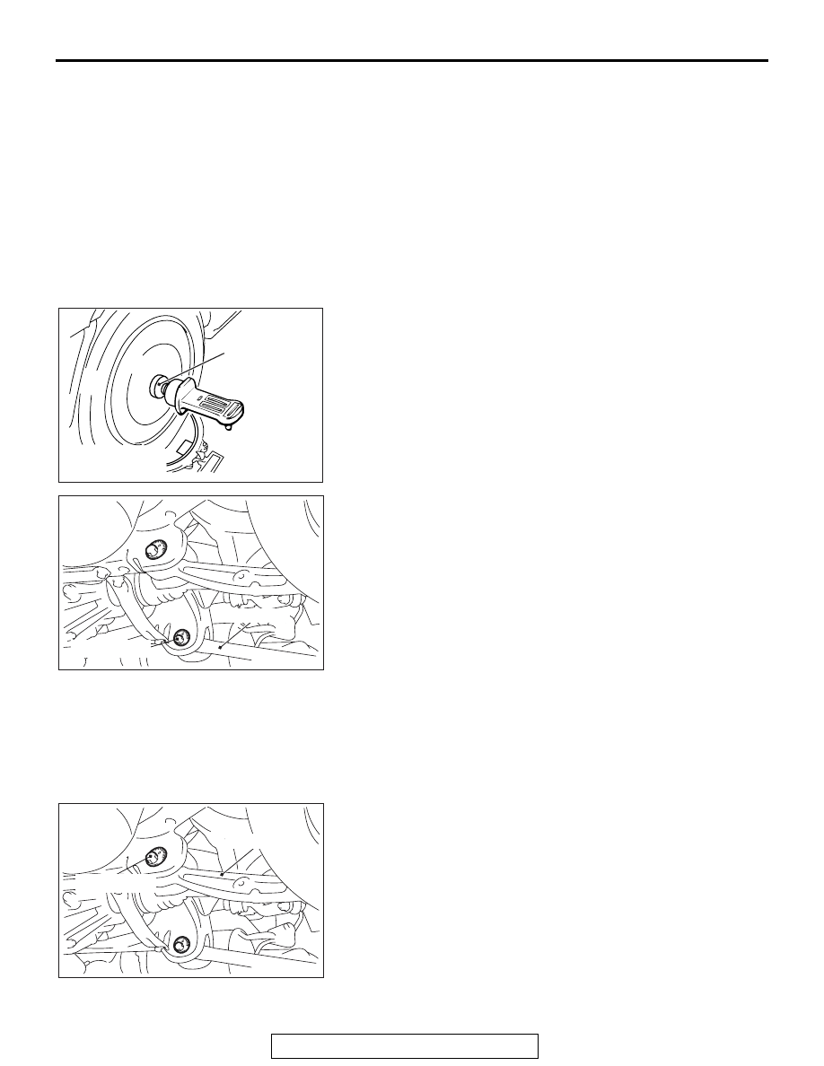
CAMBER
Standard value:
− 1° 00' ± 0° 30' (difference between left
and right within 0
° 30')
AC208980AI
MB991004
Tighten the wheel alignment gauge attachment (Special tool:
MB991004) to the specified torque, then measure the camber.
Tightening torque: 144
− 176 N⋅ m (107 − 129 ft-lb)
If camber is not within the standard value, adjust by following
procedures.
AC704801AB
Adjusting bolt
Lower arm
1. Turn the lower arm adjusting bolt (camber adjusting bolt) to
adjust.
Left wheel: Turning clockwise
→ (+) camber
Right wheel: Turning clockwise
→ (−) camber
2. After adjusting the camber, the toe should be adjusted.
.
TOE-IN
Standard value: 3
± 2 mm (0.12 ± 0.08 inch)
It toe-in is not within the standard value, adjust by following pro-
cedures.
1. Be sure to adjust the camber before making toe adjustment.
AC704801AC
Adjusting bolt
Control link
Turn the adjusting bolt (toe adjusting bolt: control link mounting
bolt which is located on the inner side of the body) to adjust.
Left wheel: Turning clockwise
→ (+) toe-in
Right wheel: Turning clockwise
→ (−) toe-in