Mitsubishi Evolution X. Manual - part 895


  Index      Mitsubishi     Mitsubishi Evolution X - service repair manual 2008 year


Search            


Content   ..  893  894  895  896   ..


Mitsubishi Evolution X. Manual - part 895


KNUCKLE

TSB Revision

REAR AXLE

27-41

REMOVAL SERVICE POINT

.

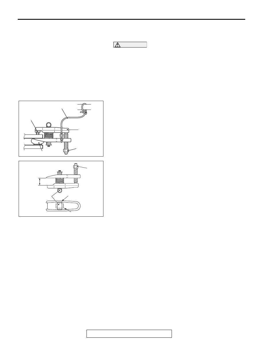
<<A>>SELF-LOCKING NUT REMOVAL

CAUTION

• Loosen the self-locking nut (trailing arm ball joint, con-

trol link ball joint, and knuckle connection) from the ball 
joint, but do not remove here. Use the special tool.

• To prevent the special tool from dropping off, suspend 

it with a rope.

• If the dust cover is damaged during operation, replace 

the dust cover. (Refer to GROUP 34 

 Control Link Ball 

Joint Dust Cover Replacement 

P.34-16

, Trailing Arm 

Ball Joint Dust Cover Replacement 

P.34-20

.)

AC208247AN

Cord

Bolt

MB991897
or
MB992011

Nut

Ball joint

1. Install special tool MB991897 or MB992011 as shown in the 

figure.

AC104739AB

Parallel

Knob

Bolt

Correct

Wrong

2. Turn the bolt and knob to make the special tool jaws parallel, 

then hand-tighten the bolt. After tightening, check that the 
jaws are still parallel.
NOTE: To adjust the special tool jaws to be parallel, set the 
orientation of the knob as shown in the figure.

3. Tighten the bolt with a wrench to disconnect the ball joint 

connection.

KNUCKLE

TSB Revision

REAR AXLE

27-42

INSTALLATION SERVICE POINT

.

>>A<< SELF-LOCKING NUT INSTALLATION

AC705237AB

Transmission
jack

Wooden
block

Self-locking
nut

Control link
assembly

AC705238AB

Self-locking
nut

Trailing arm
assembly

Transmission
jack

Wooden
block

Support the transaxle jack with a wooden block, raise the con-
trol link or trailing arm using a jack, and then tighten the 
self-locking nut.

DRIVESHAFT ASSEMBLY

TSB Revision

REAR AXLE

27-43

DRIVESHAFT ASSEMBLY

REMOVAL AND INSTALLATION

M1271003300460

CAUTION

• When removing and installing the rear wheel speed sensor, make sure that the sensor head at the 

end does not contact with surrounding parts to avoid damage.

• During maintenance, take care not to contact the parts or tools to the caliper because the paint of 

caliper will be scratched. And if there is brake fluid on the caliper, wipe off quickly.

• The parts indicated by 

*1

 should be temporarily tightened, and then fully tightened with the vehicle 

standing on the ground and the curb weight condition.

Pre-removal operation
• Gear Oil Draining (Refer to 

P.27-29

P.27-29

.)

• Center Exhaust Pipe Removal (Refer to GROUP 15, 

Exhaust Pipe Removal and Installation 

P.15-24

.)

Post-installation operation
• Check the ball joint dust cover for cracks or damage by 

pushing it with your finger.

• Center Exhaust Pipe Installation (Refer to GROUP 15, 

Exhaust Pipe Removal and Installation 

P.15-24

.)

• Gear Oil Filling (Refer to 

P.27-29

P.27-29

.)

• Wheel Alignment Check and Adjustment (Refer to 

GROUP 34, On-vehicle service 

−Rear Wheel Alignment 

Check and Adjustment 

P.34-9

 .)

The part indicated by 

*2

 is the nut with friction coefficient stabilizer. In removal, ensure there is no 

damage, clean dust and soiling from the bearing and thread surfaces, and tighten them to the 
specified torque.

AC705258

N

N

3

1

2

9

7

6

8

10

12

13

14

AB

11

7

N

144   176 N·m
107  129 ft-lb 

4

5

8.5 ± 1.5 N·m
76 ±13 in-lb

11 ± 2 N·m
98 ± 17 in-lb

11 ± 2 N·m
98 ± 17 in-lb

11 ± 2 N·m
98 ± 17 in-lb

81 ± 6 N·m
60 ± 4 ft-lb

71 ± 10 N·m
52 ± 7 ft-lb

81 ± 6 N·m
60 ± 4 ft-lb

39 ± 6 N·m
29 ± 4 ft-lb

Removal steps 

1.

Cotter pin

<<

A

>> >>

C

<< 2.

Rear driveshaft nut

>>

C

<< 3.

Washer

4.

Rear wheel speed sensor and 
brake hose fixing bolt

5.

Rear wheel speed sensor

6.

Rear brake disk (Refer to GROUP 
36, Parking Brake Lining and 
Drum 

P.36-17

.)

7.

Parking brake cable mounting bolt

8.

Knuckle, lower arm and shock 
absorber connection bolt

<<

B

>> >>

B

<< 9.

Self-locking nut (control link ball 
joint and knuckle connection)

<<

B

>> >>

B

<< 10. Self-locking nut (trailing arm ball 

joint and knuckle connection)

11. Stabilizer link and stabilizer 

connection

<<

C

>> >>

A

<< 12. Rear driveshaft assembly

13. Rear driveshaft
14. Circlip

DRIVESHAFT ASSEMBLY

TSB Revision

REAR AXLE

27-44

Required Special Tools:

• MB990242: Puller Shaft

• MB990244: Puller Bar

• MB990767: Front Hub and Flange Yoke Holder

• MB990998: Front Hub Remover and Installer

• MB991000: Spacer

• MB991354: Puller Body

• MB991897 or MB992011: Ball Joint Remover

Removal steps (Continued)


Content   ..  893  894  895  896   ..