Mitsubishi Evolution X. Manual - part 894


  Index      Mitsubishi     Mitsubishi Evolution X - service repair manual 2008 year


Search            


Content   ..  892  893  894  895   ..


Mitsubishi Evolution X. Manual - part 894


REAR AXLE HUB ASSEMBLY

TSB Revision

REAR AXLE

27-37

Required Special Tools:

• MB990211: Slide Hammer

• MB990241: Rear Axle Shaft Puller

• MB990242: Puller Shaft

• MB990244: Puller Bar

• MB990767: Front Hub and Flange Yoke Holder

• MB991354: Puller Body

REMOVAL SERVICE POINTS

.

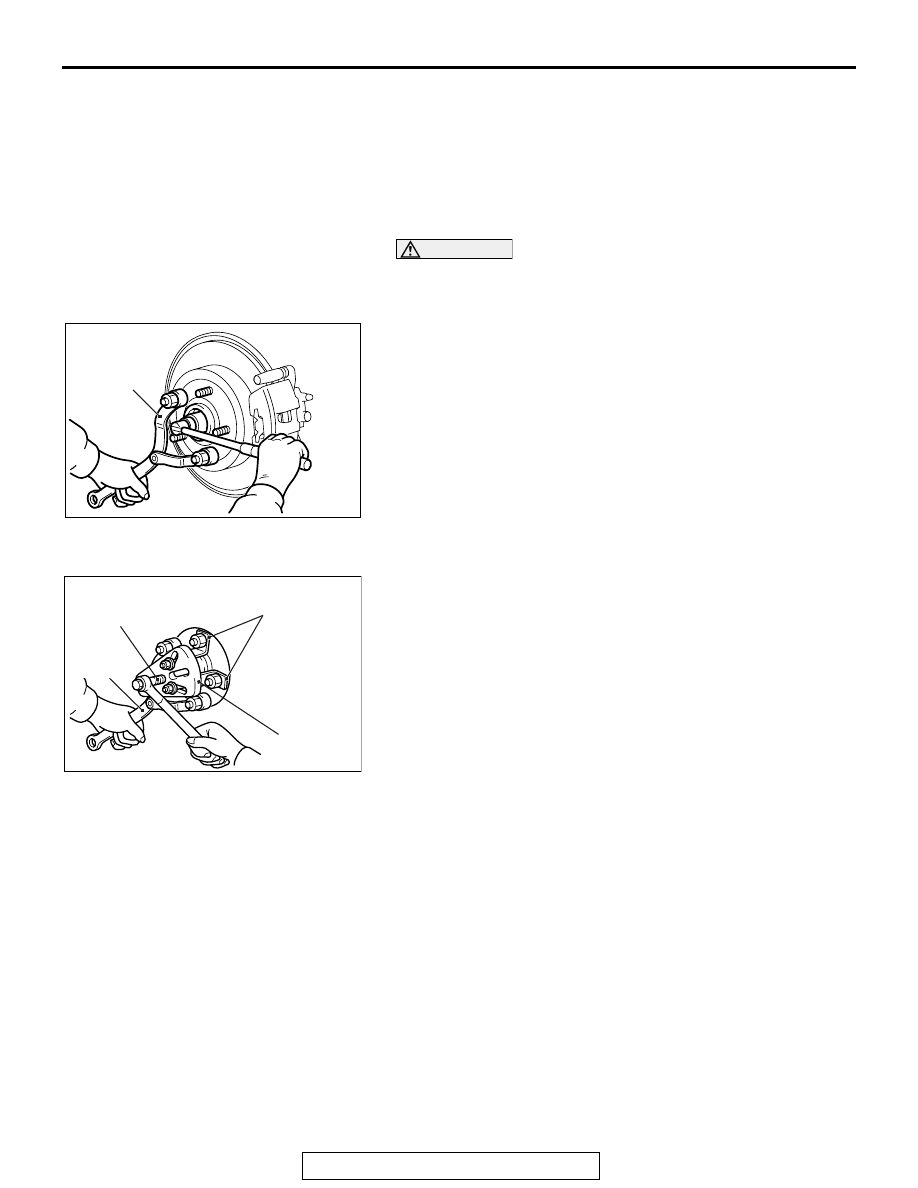
<<A>> REAR DRIVESHAFT NUT REMOVAL

CAUTION

Do not apply the vehicle weight on the rear wheel hub 
assembly with the driveshaft nut loosened. Otherwise, the 
wheel bearing will be broken.

AC205988

MB990767

AC

Use special tool MB990767 to fix the hub and remove the rear 
driveshaft nut.

.

<<B>> REAR WHEEL HUB ASSEMBLY REMOVAL

AC708477

MB991354

MB990244
(MB990241)

MB990242
(MB990241)

AC

MB990767

(Three)

1. If the rear wheel hub assembly is seized with the rear 

driveshaft assembly, use special tools MB990242 and 
MB990244, MB991354 and MB990767 to push the rear 
driveshaft assembly out from the hub and then remove the 
rear wheel hub assembly.

AC701415 AC

MB990241

MB990211

Combination (A)

AC706385 AB

MB991354

MB990211

Combination (B)

REAR AXLE HUB ASSEMBLY

TSB Revision

REAR AXLE

27-38

2. If the rear wheel hub assembly is seized with the knuckle, 

use special tools MB990211 and MB990241 {combination 
(A)}, or MB990211 and MB991354 {combination (B)} to 
remove the rear wheel hub assembly.

INSTALLATION SERVICE POINT

.

>>A<< WASHER/REAR DRIVESHAFT NUT 
INSTALLATION

CAUTION

AC608248AB

Magnetic
encoder

Rear Wheel
bearing

Rear wheel
hub
assembly

The magnetic encoder collects metallic particles easily, 
because it is magnetized. Make sure that the magnetic 
encoder should not collect metallic particles. Check 
that there is not any trouble prior to reassembling it.

• When installing the rear driveshaft, make sure that it 

does not contact with the magnetic encoder (integrated 
with the inner oil seal) to avoid damage.

• Do not apply the vehicle weight on the rear wheel bear-

ing before fully tightening the rear driveshaft nut. Oth-
erwise, the rear wheel bearing may be broken.

AC302292

AC505583

MB990767

AB

Washer

1. Be sure to install the rear driveshaft washer in the illustrated 

direction.

2. Using special tool MB990767, tighten the rear driveshaft nut. 

At this time, tighten the nut to the specified lower limit torque 
so that the pin hole may align with cotter pin.

Tightening torque: 144 

176 N⋅ m (107  129 ft-lb)

3. If the pin hole does not align with the pin, tighten the 

driveshaft nut [less than 176 N

⋅ m (129 ft-lb)] and find the 

nearest hole, then fit the cotter pin.

REAR AXLE HUB ASSEMBLY

TSB Revision

REAR AXLE

27-39

INSPECTION

M1271002100407

WHEEL BEARING ROTATION STARTING 
TORQUE AND END PLAY CHECK

Required Special Tools:

• MB990998: Front Hub Remover and Installer

• MB991000: Spacer

• MB990326: Preload Socket

AC511304 AD

MB991000

MB990998

MB990685: Torque Wrench

1. Tighten special tools MB990998 and MB991000 to the 

specified torque.

Tightening torque: 144 

176 N⋅ m (107  129 ft-lb)

2. Hold the rear wheel hub assembly in a vice with a wooden 

block.

3. Rotate the hub in order to seat the bearing.

AC206090AC

MB990326

Wooden
block

MB990685

Wooden
block

4. Measure the wheel bearing rotation starting torque by using 

special tools MB990326 and MB990685.

Limit: 1.4 N

⋅ m (12.39 in-lb)

5. If the rotation starting torque is not within the limit range, 

replace the rear wheel hub assembly. If there is any signs of 
binding or tight spots when the wheel bearing turns, also 
replace it.

AC206091AH

MB990998

Wooden 
block

Wooden 
block

6. Measure to determine whether the wheel bearing end play is 

within the specified limit or not.

Limit: 0.05 mm (0.002 inch)

7. If the play is not within the limit range while the nut is 

tightened to 144 

− 176 N⋅ m (107 − 129 ft-lb), replace the rear 

wheel hub assembly.

KNUCKLE

TSB Revision

REAR AXLE

27-40

KNUCKLE

REMOVAL AND INSTALLATION

M1271003000298

CAUTION

• The parts indicated by 

*1

 should be temporarily tightened, and then fully tightened with the vehicle 

standing on the ground and the curb weight condition.

Pre-removal operation
• Rear Wheel Hub Assembly Removal (Refer to 

P.27-36

.)

• Backing Plate Removal (Refer to GROUP 36, Parking 

Brake Lining and Drum 

P.36-17

.)

Post-installation operation
• Check the ball joint dust cover for cracks or damage by 

pushing it with your finger.

• Backing Plate Installation (Refer to GROUP 36, Parking 

Brake Lining and Drum 

P.36-17

.)

• Rear Wheel Hub Assembly Installation (Refer to 

P.27-36

.)

AC705232

N

2

1

3

N

AB

81 ± 6 N·m
60 ± 4 ft-lb

39 ± 6 N·m
29 ± 4 ft-lb

4

5

6

71 ± 10 N·m
52 ± 7 ft-lb

71 ± 10 N·m
52 ± 7 ft-lb

81 ± 6 N·m
60 ± 4 ft-lb

Removal steps 

<<

A

>> >>

A

<< 1.

Self-locking nut (trailing arm ball 
joint and knuckle connection)

<<

A

>> >>

A

<< 2.

Self-locking nut (control link ball 
joint and knuckle connection)

3.

Knuckle, lower arm and shock 
absorber connection bolt

4.

Stabilizer link and upper arm 
connection

5.

Knuckle and upper arm 
connection

6.

Knuckle assembly

The parts indicated by 

*2

 are the nuts with friction coefficient stabilizer. In removal, ensure there is 

no damage, clean dust and soiling from the bearing and thread surfaces, and tighten them to the 
specified torque.

Required Special Tools:

• MB991897 or MB992011: Ball Joint Remover

Removal steps (Continued)


Content   ..  892  893  894  895   ..