Mitsubishi Evolution X. Manual - part 883


  Index      Mitsubishi     Mitsubishi Evolution X - service repair manual 2008 year


Search            


Content   ..  881  882  883  884   ..


Mitsubishi Evolution X. Manual - part 883


PROPELLER SHAFT

TSB Revision

PROPELLER SHAFT

25-7

REMOVAL SERVICE POINTS

.

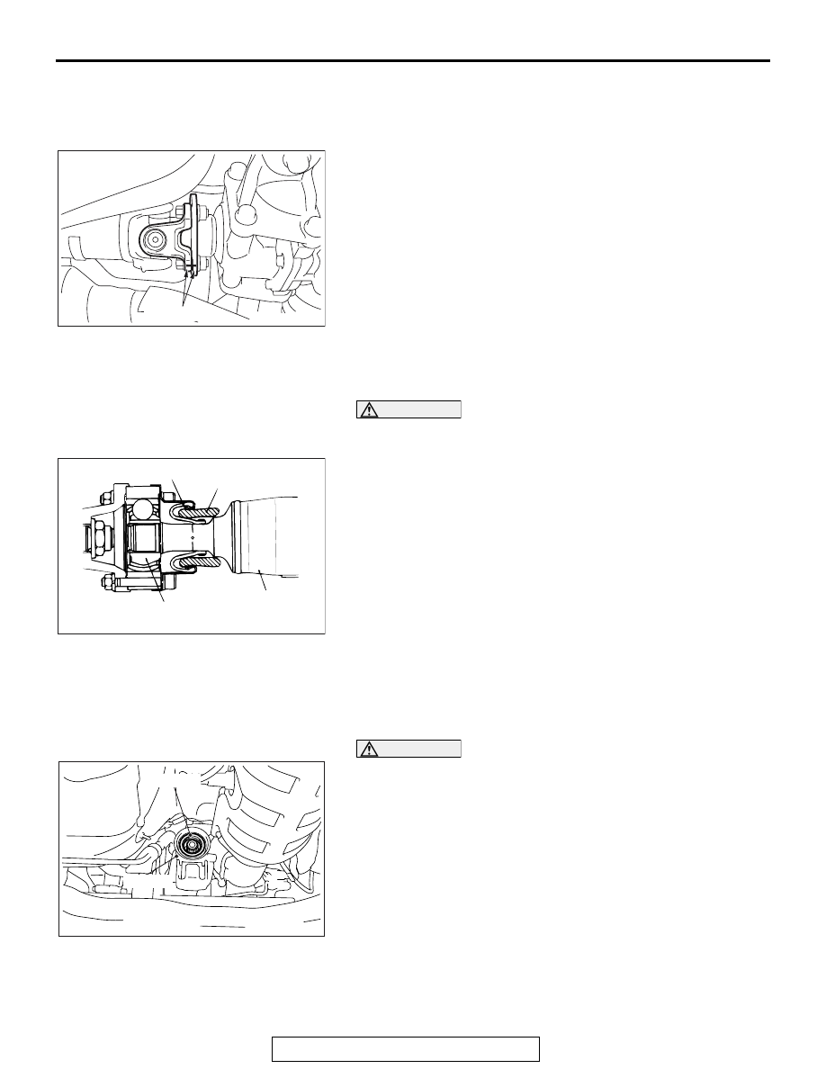
<<A>> PROPELLER SHAFT FLANGE YOKE AND 
REAR DIFFERENTIAL CONNECTION NUT

AC704938 AB

Mating marks

Put mating marks on the flange yoke and the differential com-
panion flange and remove the connecting nuts.

.

<<B>> PROPELLER SHAFT ASSEMBLY 
REMOVAL

CAUTION

If the joint assembly is bent, it may be damaged when 
pinching the joint boots.

AC101255AB

Joint Boot

Joint assembly

Rag

Rear propeller
shaft

Insert a rag or similar materials into the joint boots, and remove 
the propeller shaft assembly by aligning the front propeller shaft 
with the rear shaft. 

INSTALLATION SERVICE POINTS

.

>>A<< PROPELLER SHAFT ASSEMBLY INSTAL-
LATION

CAUTION

AC704800AB

Transfer

Oil seal

Do not damage the oil seal lip of the transfer.

• The mounting bolt and nut may be loosened if oil or 

grease is stuck on the threads of the bolt and nut. 
Tighten them after degreasing the threads.

• If the joint assembly is bent, it may be damaged when 

pinching the joint boots.

.

PROPELLER SHAFT

TSB Revision

PROPELLER SHAFT

25-8

>>B<< PROPELLER SHAFT FLANGE YOKE AND 
REAR DIFFERENTIAL CONNECTION NUT 
INSTALLATION

If the propeller shaft is reused, align the mating marks and 
install the connecting nuts.

Tightening torque: 54 

± 5 N⋅ m (40 ± 4 ft-lb)

INSPECTION

M1251001100435

.

PROPELLER SHAFT RUNOUT

ACX00643

Check the deflection of the front, center and rear shafts.

Limit: 0.5 mm (0.02 inch)

.

PROPELLER SHAFT UNIVERSAL JOINT PLAY 
CHECK

AC501206

1. Hold the tube of propeller shaft by one hand, and apply force 

by the other hand to the flange yoke or sleeve yoke in 
rotative direction, axial direction, and perpendicular direction 
for checking looseness.

2. If looseness is recognized, replace the propeller shaft with a 

new one.

PROPELLER SHAFT

TSB Revision

PROPELLER SHAFT

25-9

DISASSEMBLY AND ASSEMBLY

M1251001200249

AC704786

2

1

N

3

4

5

10

9

8

7

N

11

N

14

N

13

15

12

N

16

N

6

17

AB

54 ± 5 N·m
40 ± 4 ft-lb

14

11

16

12

13

15

14

11

12

15

14

34 ± 5 N·m
25 ± 4 ft-lb

187 ± 29 N·m
138 ± 21 ft-lb

187 ± 29 N·m
138 ± 21 ft-lb

LJ kit

LJ boot kit

Disassembly steps 

1.

Bolt

2.

Front propeller shaft assembly

>>

E

<< 3.

Self locking nut

<<

A

>> >>

E

<< 4.

Companion flange

<<

B

>> >>

E

<< 5.

Center bearing assembly

<<

C

>>

6.

Bolt

>>

D

<< 7.

Self locking nut

<<

A

>> >>

D

<< 8.

Companion flange

<<

B

>> >>

D

<< 9.

Center bearing assembly

10. Center propeller shaft

11. Snap ring

>>

C

<< 12. Boot band

<<

D

>> >>

B

<< 13. LJ assembly

14. Rubber packing

<<

E

>> >>

A

<< 15. LJ boot

16. Washer
17. Rear propeller shaft assembly

Required Special Tool:

• MD998801: Bearing Remover

Disassembly steps (Continued)

PROPELLER SHAFT

TSB Revision

PROPELLER SHAFT

25-10

LUBRICATION AND ADHESIVE POINTS

AC705050AB

Rubber
mount

Grease: repair kit grease
Amount used: 75 ± 5 g (2.6 ± 0.1 oz)

Rubber
mount

TM

Adhesive: 
3M     AAD Part No. 8730, 8731 or equivalent


Content   ..  881  882  883  884   ..