Mitsubishi Evolution X. Manual - part 882
SERVICE SPECIFICATION
TSB Revision
PROPELLER SHAFT
25-3
NOTE: *: Indicates the distance between each joint
center.
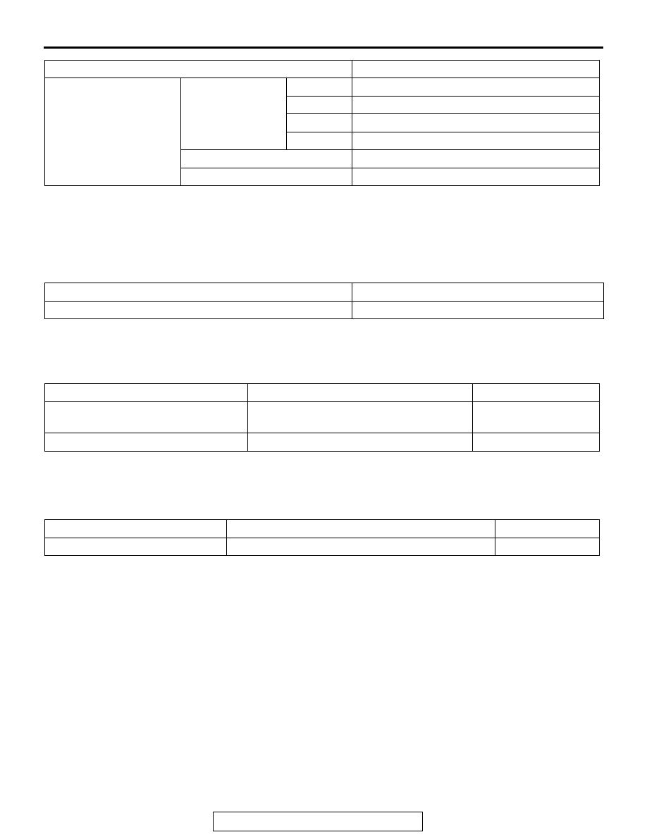
SERVICE SPECIFICATION
M1251000300373
Item
Limit
Propeller shaft runout mm (in)
0.5 (0.02)
LUBRICANTS
M1251000400507
Item
Specified lubricant
Quantity
Front propeller shaft sleeve yoke
Hypoid gear oil API classification GL-5
SAE90
as required
LJ assembly
Repair kit grease
75
± 5 g (2.6 ± 0.1 oz)
SEALANT
M1251000500151
Item
Specified sealant
Quantity
LJ assembly rubber packing
3M
™ AAD Part No. 8730, 8731 or equivalent
As required
PROPELLER SHAFT DIAGNOSIS
INTRODUCTION TO PROPELLER SHAFT DIAGNOSIS
M1251001800111
If an abnormal noise is heard from the propeller shaft
while driving, some parts of the propeller shaft may
be worn or damaged, or some mounting bolts may
be loose.
PROPELLER SHAFT DIAGNOSTIC TROUBLESHOOTING STRATEGY
M1251001900129
Use these steps to plan your diagnostic strategy. If
you follow them carefully, you will be sure that you
have exhausted all of the possible ways to find a pro-
peller shaft fault.
1. Gather information from the customer.
2. Verify that the condition described by the
customer exists.
3. Find the malfunction by following the Symptom
Chart.
4. Verify malfunction is eliminated.
Universal joint
Type
No.1
Cross type (caulking method)
No.2
Cross type (caulking method)
No.3
Constant velocity type (LJ)
No.4
Cross type (caulking method)
Bearing
Needle roller bearing (maintenance-free type)
Journal diameter mm (in)
18.0 (0.71)
Item
Specification