Mitsubishi Evolution X. Manual - part 874


  Index      Mitsubishi     Mitsubishi Evolution X - service repair manual 2008 year


Search            


Content   ..  872  873  874  875   ..


Mitsubishi Evolution X. Manual - part 874


ON-VEHICLE SERVICE

TSB Revision

POWER STEERING

37-19

POWER STEERING SYSTEM AIR BLEEDING

M1372002200909

Perform air bleeding procedure as necessary after replacing 
the steering gear or the steering fluid lines.
1. Raise and support the front wheels.

AC705444 AB

Crank angle sensor

Oil filter

2. Disconnect the crank angle sensor connector.

CAUTION

Perform air bleeding only while cranking the engine. If air 
bleeding is performed while the engine is running, air 
could enter the fluid. During air bleeding, refill the steering 
fluid supply so that the level never falls below the lower 
mark on the dipstick.
3. Turn the steering wheel all the way to the left and right five 

or six times while using the starter motor to crank the engine 
intermittently several times (for 15 to 20 seconds).

4. Connect the crank angle sensor connector.
5. Start the engine (idling).
6. Turn the steering wheel to the left and right until there are no 

air bubbles in the oil reservoir.

7. Confirm that the fluid is not milky, and that the level is 

between the high and low dipstick marks.

8. Confirm that there is very little change in the fluid level when 

the steering wheel is turned left and right.

CAUTION

If the fluid level rises suddenly after the engine is stopped, 
the air has not been completely bled. If air bleeding is not 
complete, there will be abnormal noises from the pump 
and the flow-control valve, and this condition could cause 
reduce the life of the power steering components.
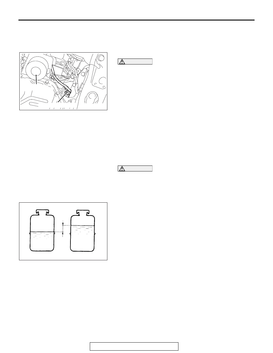
AC608306

With engine stopped

AC

Fluid level change: Within 5 mm (0.2 in)

With engine running

9. Confirm that the change in the fluid level is no more than 5 

mm (0.2 inch) when the engine is stopped and when it is 
running.

10.If the change of the fluid level is 5 mm (0.2 inch) or more, 

the air has not been completely bled from the system. The 
air bleeding procedure must be repeated.

AC608435 AD

MUT-III main harness A

V. C. I.

USB cable

Data link connector

ON-VEHICLE SERVICE

TSB Revision

POWER STEERING

37-20

11.Use the scan tool MB991958, check if the DTC is set. If it is 

set, erase it.

OIL PUMP PRESSURE TEST

M1372002300757

Required Special Tools:

• MB990662: Power Steering Oil Pressure Gauge

• MB991548: Power Steering Oil Pressure Gauge Adapter 

(Pump Side)

AC609397AB

Thermometer

Reservoir

Pressure gauge
(MB990662)

Shut-off valve

Adapter
(MB991548)

Oil
pump

Adapter
(MB991549)

MB991549: Power Steering Oil Pressure Gauge Adapter 
(Hose Side)

1. Disconnect the pressure hose from the oil pump, and then 

connect the special tools MB991548, MB990662 and 
MB991549.

2. Bleed air, then turn the steering wheel several times while 

the vehicle is not moving so that the temperature of the fluid 
rises to approximately 50 

− 60° C (122 − 140° F).

3. Start the engine and idle it at 1000 

± 100 r/min.

CAUTION

The pressure gauge shut-off valve must not remain closed 
for more than 10 seconds.
4. Fully close the shut-off valve of the pressure gauge and 

measure the oil pump relief pressure to confirm that it is 
within the standard value range. Open it again immediately 
after checking the pressure.

Standard value: 8.1 

 8.8 MPa (1,174  1,276 psi)

5. If it is not within the standard value, replace the oil pump.
6. Check whether or not the hydraulic pressure is the standard 

value when no-load conditions are created by fully opening 
the shut-off valve of the pressure gauge.

Standard value: 1.0 MPa (144 psi)

ON-VEHICLE SERVICE

TSB Revision

POWER STEERING

37-21

7. If it is not within the standard value, the probable cause is a 

malfunction of the oil line or steering gear, so check these 
parts and repair as necessary.

8. Turn the steering wheel all the way to the left or right; then 

check whether or not the retention hydraulic pressure is the 
standard value.

Standard value: 8.1 

 8.8 MPa (1,174  1,276 psi)

9. If not the standard value, overhaul the steering gear. 

Remeasure fluid pressure.

10. Remove the special tools MB991548, MB990662 and 

MB991549, and then tighten the pressure hose to the 
specified torque.

Tightening torque: 57 

± 7 N⋅ m (42 ± 5 ft-lb)

11. Bleed the system (Refer to 

P.37-19

).

POWER STEERING PRESSURE SWITCH CHECK

M1372007200647

Required Special Tools:

• MB990662: Power Steering Oil Pressure Gauge

• MB991548: Power Steering Oil Pressure Gauge Adapter 

(Pump Side)

ACX01134 AH

Thermo-
meter

Adapter
(MB991548)

Oil
 pump

Adapter
(MB991549)

Shut-off
valve

Pressure
gauge
(MB990662)

Reservoir

MB991549: Power Steering Oil Pressure Gauge Adapter 
(Hose Side)

1. Disconnect the pressure hose from the oil pump, and then 

connect the special tools MB991548, MB990662 and 
MB991549.

2. Bleed air, and then turn the steering wheel several times 

while the vehicle is not moving so that the temperature of 
the fluid rises to approximately 50

° C − 60° C (122° F − 

140

° F).

3. The engine should be idling.
4. Disconnect the connector for the oil pressure switch, and 

place an ohmmeter at the switch.

5. Gradually close the shut-off valve of the pressure gauge and 

increase the hydraulic pressure, then check whether or not 
the hydraulic pressure that activates the switch is the 
standard value.

Standard value: 8.1 

 8.8 MPa (1,174  1,276 psi)

6. Gradually open the shut-off valve and reduce the hydraulic 

pressure; then check whether or not the hydraulic pressure 
that deactivates the switch is the standard value.

Standard value: 8.1 

 8.8 MPa (1,174  1,276 psi)

7.  Remove special tools MB991548, MB990662 and 

MB991549, connect the pressure hose to the oil pump, and 
then tighten the eye bolt to the specified torque.

Tightening torque: 57 

± 7 N⋅ m (42 ± 5 ft-lb)

8. Bleed the system. (Refer to 

P.37-19

).

STEERING WHEEL

TSB Revision

POWER STEERING

37-22

STEERING WHEEL

REMOVAL AND INSTALLATION

M1372011401078

CAUTION

• Before removing the steering wheel assembly and driver's air bag module, always refer to GROUP 

52B 

 Service Precautions 

P.52B-25

 and Air bag Module and Clock Spring 

P.52B-386

.

• After removing the steering wheel, always perform a calibration for the ASC-ECU to learn the 

steering wheel sensor neutral point. (Refer to GROUP 35C 

 On-vehicle Service, Steering Wheel 

Sensor Calibration 

P.35C-267

.)

Pre-removal Operation
Steering wheel at straight-ahead position check

Post-installation Operation
• Steering wheel at straight-ahead position check

• Steering wheel looseness check

AC708304 AB

1

7

18

8

2

3

4

1

9

44 ± 11 N·m
33 ± 8 ft-lb

Craw

5

10

8

2

3

4

6

11

13

16

17

18

9.5 ± 2.5 N·m
84 ± 22 in-lb 

14

15

Craw

12

9.5 ± 2.5 N·m
84 ± 22 in-lb 

Removal steps 

<<

A

>>

1. Cover

>>

B

<<

2. Horn connector connection

>>

B

<<

3. Steering switch connector 

connection

<<

B

>>

>>

B

<<

4. Driver’s air bag module 

connector connection

5. Steering wheel voice control 

switch cover <Vehicles with 
steering wheel voice control 
switch>

6. Steering wheel voice control 

switch connector connection 
<Vehicles with steering wheel 
voice control switch>

7. Steering wheel voice control 

switch <Vehicles with steering 
wheel voice control switch>

<<

C

>>

>>

A

<<

8. Driver’s air bag module
9. Flunge nut
10. Lower cover

Removal steps (Continued)


Content   ..  872  873  874  875   ..