Mitsubishi Evolution X. Manual - part 867


  Index      Mitsubishi     Mitsubishi Evolution X - service repair manual 2008 year


Search            


Content   ..  865  866  867  868   ..


Mitsubishi Evolution X. Manual - part 867


ENGINE MOUNTING

TSB Revision

POWER PLANT MOUNT

32-5

REMOVAL SERVICE POINT

.

<<A>> ENGINE MOUNTING BRACKET REMOVAL

CAUTION

When supporting the engine and transaxle assembly by 
using the garage jack, pay attention not to deform the 
engine oil pan.
1. Place a garage jack against the engine oil pan with a piece 

of wood in between, and support the engine and transaxle 
assembly.

2. Operate the garage jack so that the engine and transaxle 

assembly weight is not applied to the engine mounting 
insulator, and then remove the engine mounting bracket.

INSTALLATION SERVICE POINT

.

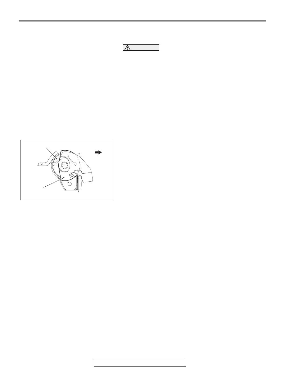
>>A<< ENGINE MOUNTING INSULATOR STOP-
PER INSTALLATION

AC710605AB

Engine side

Engine mounting insulator

Engine mounting
insulator stopper

Install the engine mounting insulator stopper as shown in the 
figure.

TRANSAXLE MOUNTING

TSB Revision

POWER PLANT MOUNT

32-6

TRANSAXLE MOUNTING

REMOVAL AND INSTALLATION

M1321001401693

Pre-removal operation
• Engine Room Under Cover Front A, B, Engine Room 

Under Cover Center and Engine Room Side Cover (LH) 

Removal (Refer to GROUP 51, Under Cover 

P.51-16

).

• Air Cleaner Assembly Removal (Refer to GROUP 15, Air 

Cleane

P.15-10

).

• Engine Control Module (ECM) Removal (Refer to GROUP 

13A, Engine Control Module (ECM) 

P.13A-920

).

• Engine control harness connector bracket Removal 

(Refer to GROUP 54A, Battery 

P.54A-10

).

• Relay box mounting bolts Removal.

Post-installation operation
• Relay box mounting bolts Installation.

• Engine control harness connector bracket Installation 

(Refer to GROUP 54A, Battery 

P.54A-10

).

• Engine Control Module (ECM) Installation (Refer to 

GROUP 13A, Engine Control Module (ECM) 

P.13A-920

).

• Air Cleaner Assembly Installation (Refer to GROUP 15, 

Air Cleaner 

P.15-10

).

• Engine Room Under Cover Front A, B, Engine Room 

Under Cover Center and Engine Room Side Cover (LH) 

Installation (Refer to GROUP 51, Under Cover 

P.51-16

).

AC709069

1

2

2

3

AB

50 ± 5 N·m
37 ± 3 ft-lb 

47 ± 7 N·m
35 ± 5 ft-lb 

95 ± 10 N·m
71 ± 7 ft-lb

50 ± 5 N·m
37 ± 3 ft-lb 

<M/T>

<TC-SST>

50 ± 5 N·m
37 ± 3 ft-lb 

50 ± 5 N·m
37 ± 3 ft-lb 

2

3

2

95 ± 10 N·m
71 ± 7 ft-lb

1

47 ± 7 N·m
35 ± 5 ft-lb 

Removal steps 

<<

A

>>

1.

Transaxle mounting bracket

>>

A

<<

2.

Transaxle mounting insulator 
stopper

3.

Transaxle mounting insulator

Removal steps (Continued)

TRANSAXLE MOUNTING

TSB Revision

POWER PLANT MOUNT

32-7

REMOVAL SERVICE POINT

.

<<A>> TRANSAXLE MOUNTING BRACKET 
REMOVAL

1. Place a garage jack against the transaxle case with a piece 

of wood in between, and support the engine and transaxle 
assembly.

2. Operate the garage jack so that the engine and transaxle 

assembly weight is not applied to the transaxle mounting 
insulator, and then remove the transaxle mounting bracket.

INSTALLATION SERVICE POINT

.

>>A<< TRANSAXLE MOUNTING INSULATOR 
STOPPER INSTALLATION

AC708342

AB

Transaxle side

Transaxle 
mounting 
insulator

Transaxle mounting 
insulator stopper

Install the transaxle mounting insulator stopper as shown in the 
figure.

FRONT ROLL STOPPER AND CENTERMEMBER

TSB Revision

POWER PLANT MOUNT

32-8

FRONT ROLL STOPPER AND CENTERMEMBER

REMOVAL AND INSTALLATION

M1321005800032

CAUTION

• The part indicated by the *

1

 mark should be temporarily tightened, and then fully tightened with 

the engine and transaxle assembly weight applied on the vehicle body.

Pre-removal and post-installation operation
• Engine Room Under Cover Front A, B and Engine Room 

Under Cover Center Removal and Installation (Refer to 

GROUP 51, Under Cover 

P.51-16

).

AC710612

1

53 ± 8 N·m*
40 ± 5 ft-lb* 

1

1

AC

4

3

2

71 ± 10 N·m*
52 ± 7 ft-lb* 

2

2

71 ± 10 N·m*
52 ± 7 ft-lb* 

2

2

50 ± 5 N·m
37 ± 3 ft-lb

28 ± 4 N·m
21 ± 2 ft-lb 

Removal steps 

1.

Front axle crossmember bar

2.

Centermember and front roll 
stopper assembly

3.

Centermember

>>

A

<<

4.

Front roll stopper

The parts indicated by the *

2

 are the bolts with friction coefficient stabilizer. In removal, ensure 

there is no damage, clean dust and soiling from bearing and thread surfaces, and tighten them to 
the specified torque.

Removal steps (Continued)


Content   ..  865  866  867  868   ..