Mitsubishi Evolution X. Manual - part 853
FRONT AXLE HUB ASSEMBLY
TSB Revision
FRONT AXLE
26-13
>>B<< WASHER/FRONT DRIVESHAFT NUT
INSTALLATION
CAUTION
•
AC704652 AB
Oil seal
Magnetic
encoder
Wheel
bearing
Hub
The magnetic encoder collects metallic particles easily,
because it is magnetized. Make sure that the magnetic
encoder should not collect metallic particles. Check
that there is not any trouble prior to reassembling it.
• When installing the front driveshaft, make sure that it
does not contact with the magnetic encoder (integrated
with the inner oil seal) to avoid damage.
• Do not apply the vehicle weight on the wheel bearing
before fully tightening the front driveshaft nut. Other-
wise, the wheel bearing may be broken.
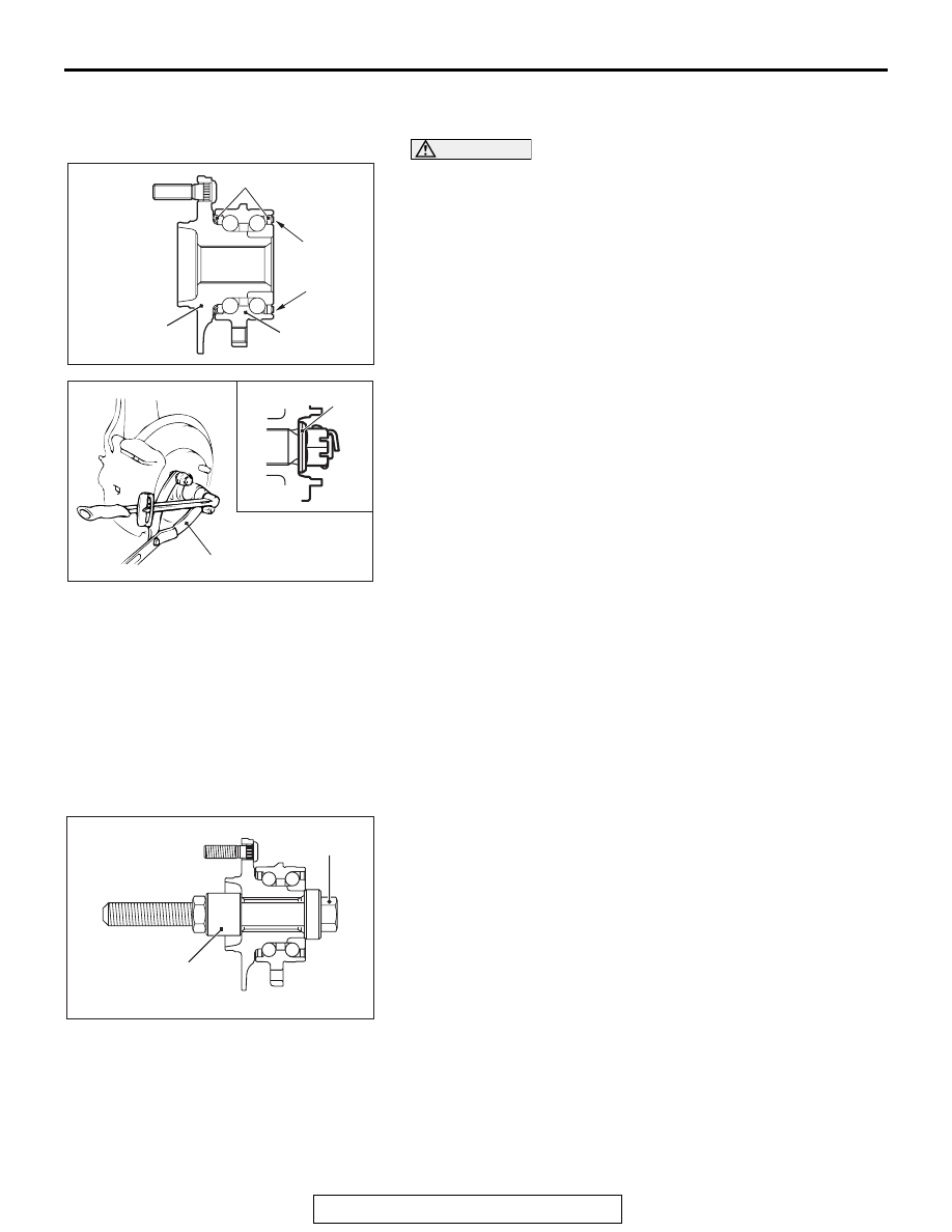
AC608310 AB
MB990767
Washer
1. Be sure to install the front driveshaft washer in the illustrated
direction.
2. Using special tool MB990767, tighten the driveshaft nut. At
this time, tighten the nut to the specified lower limit torque so
that the pin hole may align with cotter pin.
Tightening torque: 144
− 176 N⋅ m (107 − 129 ft-lb)
3. If the pin hole does not align with the pin, tighten the
driveshaft nut [less than 176 N
⋅ m (129 ft-lb)] and find the
nearest hole, then fit the cotter pin.
INSPECTION
M1261001800435
WHEEL BEARING ROTATION STARTING
TORQUE AND END PLAY CHECK
Required Special Tools:
• MB990998: Front Hub Remover and Installer
• MB991000: Spacer
• MB990326: Preload Socket
•
AC301927AB
MB991000
MB990998
MB990685: Torque Wrench
1. Tighten special tools MB990998 and MB991000 to the
specified torque.
Tightening torque: 144
− 176 N⋅ m (107 − 129 ft-lb)
2. Hold the front wheel hub assembly in a vice with a wooden
block.
3. Rotate the hub in order to seat the bearing.