Mitsubishi Evolution X. Manual - part 775


  Index      Mitsubishi     Mitsubishi Evolution X - service repair manual 2008 year


Search            


Content   ..  773  774  775  776   ..


Mitsubishi Evolution X. Manual - part 775


DIAGNOSIS

TSB Revision

ACTIVE SKID CONTROL SYSTEM (ASC)

35C-107

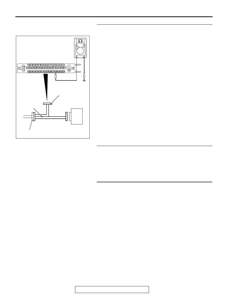
STEP 6. Resistance measurement at A-05 ASC-ECU 
connector
(1) Disconnect the ASC-ECU connector, connect the ASC 

check harness (Special tool: MB991997) to the wiring 
harness-side connector, and then measure at the special 
tool connector side.
NOTE: Do not connect the special tool to ASC-ECU.

(2) Measure the resistance between the wheel speed sensor 

circuit power supply terminal (signal terminal) No. 36 and 
the body ground as well as between the ground terminal 
No. 37 and the body ground.

OK: No continuity

Q: Is the check result normal?

YES  : Go to Step 9.
NO (Not normal at the terminal No. 36 or 37) : Go to Step 

7.

STEP 7. Connector check: A-05 ASC-ECU connector, C-45 
intermediate connector, D-18 wheel speed sensor <RL> 
connector
Q: Is the check result normal?

YES : Go to Step 8.
NO :  Repair the defective connector. Then go to Step 17.

STEP 8. Wiring harness check between A-05 ASC-ECU 
connector terminal No. 36 and D-18 wheel speed sensor 
<RL> connector terminal No. 1, and between A-05 
ASC-ECU connector terminal No. 37 and D-18 wheel speed 
sensor <RL> connector terminal No. 2

• Short circuit check of wheel speed sensor <RL> circuit

Q: Is the check result normal?

YES : Replace the wheel speed sensor <RL>. (Refer to 

P.35C-274

.) Then go to Step 17.

NO :  Repair the wiring harness. Then go to Step 17.

AC400817CI

ASC-ECU

MB991997

Check harness

A-05 ASC-ECU
harness connector

DIAGNOSIS

TSB Revision

ACTIVE SKID CONTROL SYSTEM (ASC)

35C-108

STEP 9. Voltage measurement at A-05 ASC-ECU connector
(1) Disconnect the ASC-ECU connector, connect the ASC 

check harness (Special tool: MB991997) to the 
ASC-ECU-side connector and the wiring harness-side 
connector, and then measure at the special tool connector 
side.

(2) Turn the ignition switch to the ON position.
(3) Measure the voltage between the wheel speed sensor 

circuit power supply terminal (signal terminal) No. 36 and 
the body ground.

OK: System voltage

Q: Is the check result normal?

YES : Go to Step 10.
NO :  Go to Step 12.

STEP 10. Wiring harness check between A-05 ASC-ECU 
connector terminal No. 36 and D-18 wheel speed sensor 
<RL> connector terminal No. 1, and between A-05 
ASC-ECU connector terminal No. 37 and D-18 wheel speed 
sensor <RL> connector terminal No. 2

• Open circuit check of wheel speed sensor <RL> circuit

Q: Is the check result normal?

YES : Go to Step 11.
NO :  Repair the wiring harness. Then go to Step 17.

STEP 11. Check of wheel speed sensor as a single unit
Refer to 

P.35C-277

.

Q: Is the check result normal?

YES : Go to Step 13.
NO :  Replace the wheel speed sensor <RL>. (Refer to 

P.35C-274

.) Then go to Step 17.

STEP 12. Connector check: A-05 ASC-ECU connector, 
C-45 intermediate connector, D-18 wheel speed sensor 
<RL> connector
Q: Is the check result normal?

YES : Go to Step 16.
NO :  Repair the defective connector. Then go to Step 17.

AC400817CJ

ASC-ECU

MB991997

Check harness

A-05 ASC-ECU
harness connector

DIAGNOSIS

TSB Revision

ACTIVE SKID CONTROL SYSTEM (ASC)

35C-109

STEP 13. Check of wheel speed sensor installation status
Check the installation status of wheel speed sensor <RL> (dis-
connection of wheel speed sensor, looseness of mounting bolt, 
etc.).
Q: Is the check result normal?

YES : Go to Step 14.
NO :  Reinstall the wheel speed sensor <RL> correctly. 

(Refer to 

P.35C-274

.) Then go to Step 17.

STEP 14. Wheel bearing looseness check
NOTE: Wheel bearing looseness may increase the gap 
between the wheel speed sensor and the wheel speed detec-
tion magnet encoder. Check the wheel bearing <RL> for loose-
ness. (Refer to GROUP 27 

 On-vehicle Service 

P.27-33

.)

Q: Is the check result normal?

YES : Go to Step 15.
NO :  Replace the rear wheel hub assembly. (Refer to 

GROUP 27 

− Rear Axle Hub Assembly 

P.27-36

.)

STEP 15. Check of wheel speed detection encoder
Check the encoder for adhesion of foreign materials or defor-
mation.
Q: Is the check result normal?

YES : Go to Step 16.
NO (Adhesion of foreign materials) : Clean the encoder 

so as not to disturb the magnetization pattern on the 
encoder while taking care of the magnet, magnetic 
substance, and magnetic attraction.

NO (Deformation) : Replace the rear wheel hub assembly. 

(Refer to GROUP 27 

− Rear Axle Hub Assembly 

P.27-36

.)

STEP 16. Check whether the DTC is reset.
Drive the vehicle at 12mph (20 km/h) or more.
NOTE: The ABS warning light does not turn OFF in some 
cases unless the vehicle runs at 12mph (20 km/h) or higher.
Q: Is DTC C1048 set?

YES : Replace the hydraulic unit (incorporates in 

ASC-ECU).(Refer to 

P.35C-272

.) Then go to Step 17.

NO :  Intermittent malfunction. (Refer to GROUP 00 

− How 

to Cope with Intermittent Malfunction 

P.00-15

.)

STEP 17. Check whether the DTC is reset.
Drive the vehicle at 12mph (20 km/h) or more.
NOTE: The ABS warning light does not turn OFF in some 
cases unless the vehicle runs at 12mph (20 km/h) or higher.
Q: Is DTC C1048 set?

YES : Return to Step 1.
NO :  This diagnosis is complete.

AC608248AB

Magnetic
encoder

Rear Wheel
bearing

Rear wheel
hub
assembly

DIAGNOSIS

TSB Revision

ACTIVE SKID CONTROL SYSTEM (ASC)

35C-110

DTC C1049: RR wheel speed sensor control phase time exceeded

CAUTION

• If there is any problem in the CAN bus lines, an incor-

rect diagnostic trouble code may be set. Prior to this 
diagnosis, diagnose the CAN bus lines.

• Whenever the ECU is replaced, ensure that the CAN 

bus lines are normal.

• When the hydraulic unit (integrated with ASC-ECU) is 

replaced, always perform the calibration of steering 
wheel sensor, G and yaw rate sensor, brake fluid pres-
sure sensor, cut valve, and inlet valve.(Refer to 

P.35C-266

P.35C-267

P.35C-268

, and 

P.35C-269

.)

.

CIRCUIT OPERATION

• Each wheel speed detecting section is a kind of a pulse 

generator. It consists of the encoder (plate on which the 
north and south pole of magnet are arranged alternately) for 
detecting the wheel speed, which rotates at the same speed 
of the wheels, and the wheel speed sensor. This detecting 
section outputs the frequency pulse signals in proportion to 
the wheel speed.

• The pulse signals generated by the wheel speed detecting 

section are sent to ASC-ECU. ASC-ECU uses the fre-
quency of the pulse signals to determine the wheel speed.

.

AC708948

Connector: A-05

A-05 (B)

AB

AC708950

Connector: C-47

AE

AC708955

Connector: D-09

D-09 (B)

AH


Content   ..  773  774  775  776   ..