Mitsubishi Evolution X. Manual - part 762
DIAGNOSIS
TSB Revision
ACTIVE SKID CONTROL SYSTEM (ASC)
35C-55
DTC C1027: Abnormality in RL wheel speed sensor signal
CAUTION
• If there is any problem in the CAN bus lines, an incor-
rect diagnostic trouble code may be set. Prior to this
diagnosis, diagnose the CAN bus lines.
• Whenever the ECU is replaced, ensure that the CAN
bus lines are normal.
• When the hydraulic unit (integrated with ASC-ECU) is
replaced, always perform the calibration of steering
wheel sensor, G and yaw rate sensor, brake fluid pres-
sure sensor, cut valve, and inlet valve.(Refer to
.)
.
CIRCUIT OPERATION
• Each wheel speed detecting section is a kind of a pulse
generator. It consists of the encoder (plate on which the
north and south pole of magnet are arranged alternately) for
detecting the wheel speed, which rotates at the same speed
of the wheels, and the wheel speed sensor. This detecting
section outputs the frequency pulse signals in proportion to
the wheel speed.
• The pulse signals generated by the wheel speed detecting
section are sent to ASC-ECU. ASC-ECU uses the fre-
quency of the pulse signals to determine the wheel speed.
.
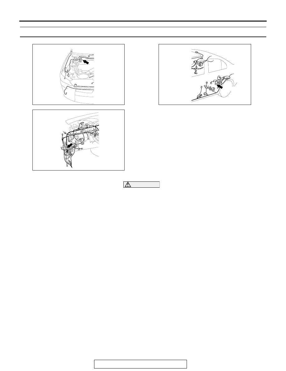
AC708948
Connector: A-05
A-05 (B)
AB
AC708950
Connector: C-45
AD
AC708955
Connector: D-18
D-18 (B)
AE