Mitsubishi Evolution X. Manual - part 739
SIDE IMPACT SENSOR
TSB Revision
SUPPLEMENTAL RESTRAINT SYSTEM (SRS)
52B-403
REMOVAL SERVICE POINTS
.
<<A>> NEGATIVE (
−) BATTERY CABLE DISCON-
NECTION
DANGER
Wait at least 60 seconds after disconnecting the bat-
tery cable before doing any further work (Refer to
).
WARNING
Battery posts, terminals and related accessories con-
tain lead and lead compounds. WASH HANDS AFTER
HANDLING.
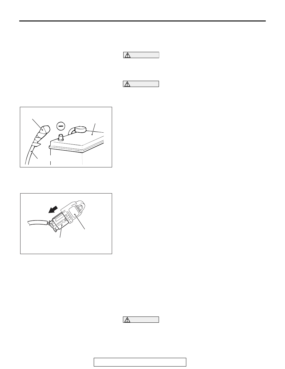
Disconnect the negative (
−) battery cable from the battery and
tape the terminal to prevent accidental connection and air bag
deployment.
.
<<B>> SIDE IMPACT SENSOR CONNECTOR
REMOVAL
Slide the outer housing of the impact sensor connector in the
arrow direction shown, and disconnect the connector.
INSTALLATION SERVICE POINTS
.
>>A<< PRE-INSTALLATION INSPECTION
Check the side impact sensor for dents, breakage and bending
and measure the resistance between the terminals, even when
installing a new side impact sensor.
.
>>B <<SIDE IMPACT SENSOR INSTALLATION
WARNING
If the side impact sensor is not installed securely and
correctly, the side-air bag may not operate normally.
Securely connect the connector.
.
ACX00583
Insulating tape
Battery cable
Battery
AF
AC709474
Side impact sensor
Outer housing of the
impact sensor
connector
AB