Mitsubishi Evolution X. Manual - part 735
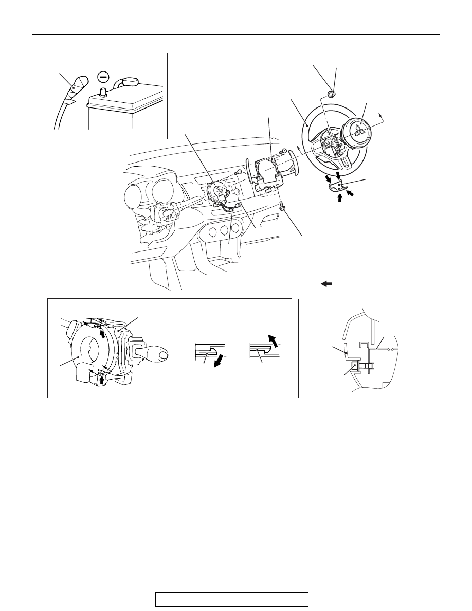
DRIVER'S AIR BAG MODULE AND CLOCK SPRING
TSB Revision
SUPPLEMENTAL RESTRAINT SYSTEM (SRS)
52B-387
AC709088 AB
1
44 ± 11 N·m
33 ± 8 ft-lb
5
2
4
3
8
7
9
7.0 ± 3.0 N·m
62 ± 27 in-lb
Section A - A
Section B - B
Section C - C
Column switch
A
A
B
B
Claw
Claw
9.5 ± 2.5 N·m
84 ± 22 in-lb
C
C
Note
: Indicates claw position
Steering wheel
lower cover
6
9
Driver air bag
module bracket
Driver's air bag module removal
steps
<<
A
>>
1.
Negative (
−) battery cable
<<
B
>>
2.
Cover
3.
Horn connector
<<
C
>>
4.
Driver's air bag module connector
<<
D
>>
5.
Driver's air bag module
Driver's air bag module
installation steps
>>
A
<<
•
Pre-installation inspection
>>
C
<<
5.
Driver's air bag module
>>
D
<<
4.
Driver's air bag module connector
>>
D
<<
3.
Horn connector
2.
Cover
1.
Negative (
−) battery cable
>>
E
•
Post-installation inspection
Clock spring removal steps
<<
A
>>
1.
Negative (
−) battery cable
<<
B
>>
2.
Cover
3.
Horn connector
<<
C
>>
4.
Driver's air bag module connector
<<
D
>>
5.
Driver's air bag module
6.
Flange nut
<<
E
7.
Steering wheel assembly
•
Lower, upper column cover (Refer
to Group 37 Steering Shaft
8.
Paddle shift assembly <vehicles
with paddle shift>
<<
F
9.
Clock spring
Clock spring installation steps
>>
A
Pre-installation inspection
>>
B
9.
Clock spring