Mitsubishi Evolution X. Manual - part 727
SRS AIR BAG DIAGNOSIS
TSB Revision
SUPPLEMENTAL RESTRAINT SYSTEM (SRS)
52B-355
DTC U0245: Audio Visual Navigation Unit CAN timeout
CAUTION
• If DTC U0245 is set in the occupant classifica-
tion-ECU, always diagnose the CAN main bus
lines.
• When replacing the ECU, always check that
the communication circuit is normal.
.
DIAGNOSTIC FUNCTION
When the signals from audio visual navigation unit
cannot be received, the occupant classification sys-
tem sets DTC U0245.
.
JUDGMENT CRITERIA
Because of the CAN-B bus circuit malfunction, if
audio visual navigation becomes unable to perform
the normal data transmission, occupant classifica-
tion-ECU determines that an abnormality is present.
.
TROUBLESHOOTING HINTS
• The CAN bus line may be defective.
• The occupant classification-ECU may be defec-
tive.
• The audio visual navigation unit may be defec-
tive.
DIAGNOSIS
Required Special Tools:
• MB991958: Scan Tool (M.U.T.-III Sub Assembly)
• MB991824: Vehicles Communication Interface (V.C.I.)
• MB991827: M.U.T.-III USB Cable
• MB991910: M.U.T.-III Main Harness A (Vehicles with
CAN communication system)
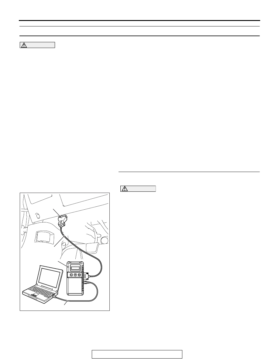
STEP 1. Using scan tool MB991958, diagnose the CAN bus
line.
CAUTION
To prevent damage to scan tool MB991958, always turn the
ignition switch to the "LOCK" (OFF) position before con-
necting or disconnecting scan tool MB991958.
(1) Connect scan tool MB991958. Refer to "How to connect the
Scan Tool (M.U.T.-III)
(2) Turn the ignition switch to the "ON" position.
(3) Diagnose the CAN bus line.
(4) Turn the ignition switch to the "LOCK" (OFF) position.
Q: Is the CAN bus line found to be normal?
YES : Go to Step 2.
NO : Repair the CAN bus line (Refer to GROUP 54C,
).
AC608435
Data link connector
MB991827
MB991824
MB991910
AB