Mitsubishi Evolution X. Manual - part 681
SRS AIR BAG DIAGNOSIS
TSB Revision
SUPPLEMENTAL RESTRAINT SYSTEM (SRS)
52B-171
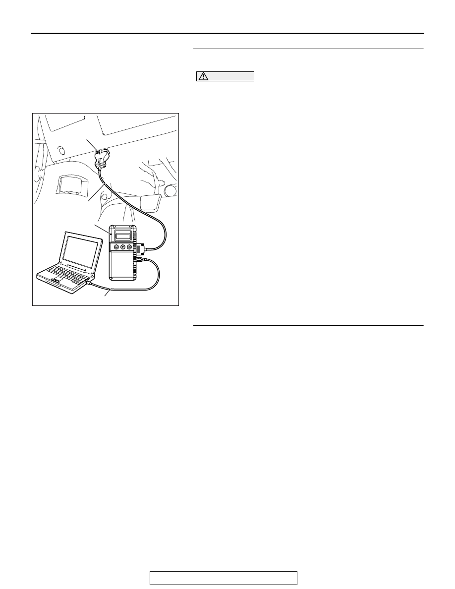
STEP 1. Using scan tool MB991958, diagnose the CAN bus
line.
CAUTION
To prevent damage to scan tool MB991958, always turn the
ignition switch to the "LOCK" (OFF) position before con-
necting or disconnecting scan tool MB991958.
(1) Connect scan tool MB991958. Refer to "How to connect the
."
(2) Turn the ignition switch to the "ON" position.
(3) Diagnose the CAN bus line.
(4) Turn the ignition switch to the "LOCK" (OFF) position.
Q: Is the CAN bus line found to be normal?
YES : Go to Step 2.
NO : Repair the CAN bus line (Refer to GROUP 54C,
).
STEP 2. Check the side impact sensor.
(1) Disconnect the negative battery terminal.
(2) A side impact sensor is checked in the following way.
• Replace the left side impact sensor {In case of code
B1B72 (Regardless of "Active" or "Stored" faults)} with
the new parts.
• Replace the right side impact sensor {In case of code
B1B75 (Regardless of "Active" or "Stored" faults)} with
the new parts.
(3) Connect the negative battery terminal.
(4) After erasing the diagnostic trouble code memory, check the
diagnostic trouble code again.
Q: Is either DTC No. B1B72 or B1B75 set?
YES : Go to Step 3.
NO : The procedure is complete.
AC608435
Data link connector
MB991827
MB991824
MB991910
AB