Mitsubishi Evolution X. Manual - part 679


  Index      Mitsubishi     Mitsubishi Evolution X - service repair manual 2008 year


Search            


Content   ..  677  678  679  680   ..


Mitsubishi Evolution X. Manual - part 679


SRS AIR BAG DIAGNOSIS

TSB Revision

SUPPLEMENTAL RESTRAINT SYSTEM (SRS)

52B-163

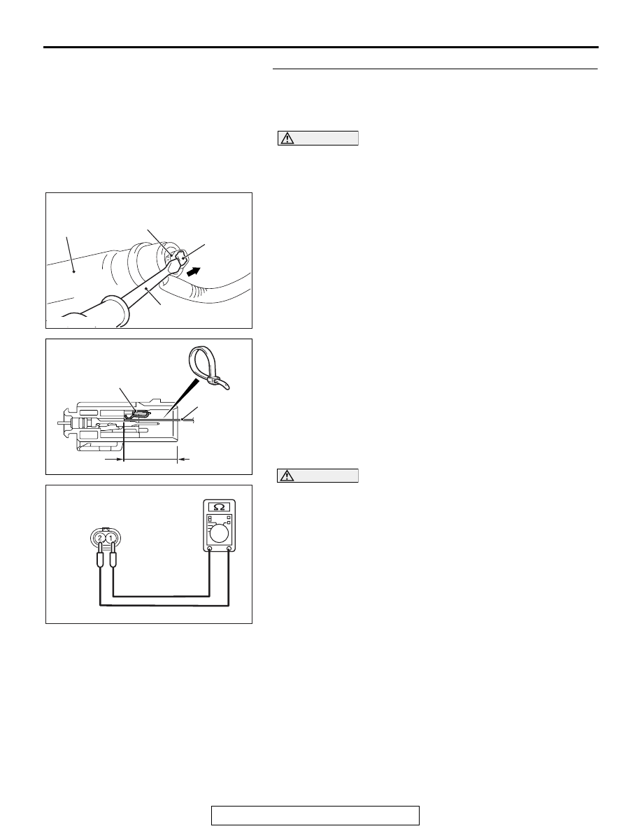
STEP 6. Short circuit check between the F-04 curtain air 
bag module harness side connector and the D-10 
intermediate harness.
(1) Disconnect the negative battery terminal.

DANGER

To prevent the air bag from deploying unintentionally, 
disconnect the curtain air bag module connector F-04 
to short the squib circuit.

(2) Disconnect curtain air bag module (RH) F-04. Use a 

flat-tipped screwdriver to unlock the locking button at the 
harness side connector by withdrawing it toward you in two 
stages, and then disconnect the connector.

(3) Disconnect the D-10 intermediate connector (connection 

between curtain air bag harness and floor harness).

(4) Because the short spring is installed to the D-10 

intermediate connector (curtain air bag harness side), insert 
a cable tie [3 mm (0.12 inch) wide, 0.5 mm (0.02 inch) thick] 
between terminals 1, 2 and the short spring to release the 
short spring.

CAUTION

Do not insert a probe into the terminal from its front side 
directly, as the connector contact pressure may be weak-
ened.
(5) Check for continuity between the D-10 intermediate 

connector (curtain air bag harness side) terminal No.1 and 
2.
It should be open circuit.

Q: Is it open circuit?

YES : Replace the curtain air bag module (RH) (Refer to 

P.52B-409

). Then go to Step 7. 

NO :  Repair the wiring harness. 

AC609834AB

Locking 
button

Flat-tipped 
screwdriver

Inflator

Curtain air bag wiring 
harness connector

AC700119

D-10 Intermediate 
connector (module side ) 

22 mm or more

Cable tie

Short spring

AJ

AC608812GZ

D-10 Intermediate connector 
(Curtain air bag harness side)
(rear view)

SRS AIR BAG DIAGNOSIS

TSB Revision

SUPPLEMENTAL RESTRAINT SYSTEM (SRS)

52B-164

STEP 7. Recheck for diagnostic trouble code. 
Check again if the DTC is set.
(1) Erase the DTC.
(2) Turn the ignition switch to the "ON" position.
(3) Check if the DTC is set.
(4) Turn the ignition switch to the "LOCK" (OFF) position.
Q: Is DTC B1B23 set?

YES : Replace SRS-ECU (Refer to 

P.52B-383

).

NO :  Intermittent Malfunction (Refer to GROUP 00, How to 

Use Troubleshooting/Inspection Service Points 

− How 

to Cope with Intermittent Malfunction 

P.00-15

).

DTC B1B54: Seat Belt Switch (RH) Circuit (Ground Side) Shorted 


DTC B1B55: Seat Belt Switch (RH) Circuit (Power Supply Side) Shorted


DTC B1B56: Seat Belt Switch (RH) Circuit Open 

SEAT BELT BUCKLE 
SWITCH 
PASSENGER'S 
SIDE

SRS-ECU

HALL IC

Seat Belt Switch Circuit

SEAT BELT WARNING 
TONE ALARM

SRS AIR BAG DIAGNOSIS

TSB Revision

SUPPLEMENTAL RESTRAINT SYSTEM (SRS)

52B-165

CAUTION

If DTC B1B54, B1B55 or B1B56 are set in the 
SRS-ECU, always diagnose the CAN main bus 
lines.

.

CIRCUIT OPERATION

The SRS-ECU determines whether the seat belt is 
fastened or not according to the connection location 
of the seat belt switch in the seat buckle.

.

DTC SET CONDITIONS

DTC is set when the resistance between input termi-
nals of the seat belt switch in the SRS-ECU is with-
out the standard value.

.

TROUBLESHOOTING HINTS

• Malfunction of the seat belt switch

• Damaged wiring harnesses or connectors 

• Malfunction of the SRS-ECU 

DIAGNOSIS

Required Special Tools:

• MB991222: Probe

• MB991958: Scan Tool (M.U.T.-III Sub Assembly)

• MB991824: Vehicle Communication Interface (V.C.I.)

• MB991827: M.U.T.-III USB Cable

• MB991910: M.U.T.-III Main Harness A (Vehicles with 

CAN communication system)

AC708951AD

Connector: C-36

C-36 (Y)

AC708954 AC

Connector: D-37

D-37 (B)

SRS AIR BAG DIAGNOSIS

TSB Revision

SUPPLEMENTAL RESTRAINT SYSTEM (SRS)

52B-166

STEP 1. Using scan tool MB991958, diagnose the CAN bus 
line.

CAUTION

To prevent damage to scan tool MB991958, always turn the 
ignition switch to the "LOCK" (OFF) position before con-
necting or disconnecting scan tool MB991958.
(1) Connect scan tool MB991958. Refer to "How to connect the 

scan tool 

P.52B-28

."

(2) Connect scan tool MB991958 to the data link connector.
(3) Turn the ignition switch to the "ON" position.
(4) Diagnose the CAN bus line.
(5) Turn the ignition switch to the "LOCK" (OFF) position.
Q: Is the CAN bus line found to be normal?

YES : Go to Step 2.
NO :  Repair the CAN bus line (Refer to GROUP 54C, 

Diagnosis 

P.54C-14

).

STEP 2. Recheck for diagnostic trouble code.
Check again if the DTC is set.
(1) Erase the DTC.
(2) Turn the ignition switch to "ON" position.
(3) Check if the DTC is set.
(4) Turn the ignition switch to the "LOCK" (OFF) position.
Q: Is the DTC set?

YES : Go to Step 3
NO :  There is an intermittent malfunction such as poor 

engaged connector(s) or open circuit (Refer to 
GROUP 00, How to Cope with Intermittent 
Malfunction 

P.00-15

).

AC608435

Data link connector

MB991827

MB991824

MB991910

AB


Content   ..  677  678  679  680   ..