Mitsubishi Evolution X. Manual - part 670


  Index      Mitsubishi     Mitsubishi Evolution X - service repair manual 2008 year


Search            


Content   ..  668  669  670  671   ..


Mitsubishi Evolution X. Manual - part 670


SRS AIR BAG DIAGNOSIS

TSB Revision

SUPPLEMENTAL RESTRAINT SYSTEM (SRS)

52B-127

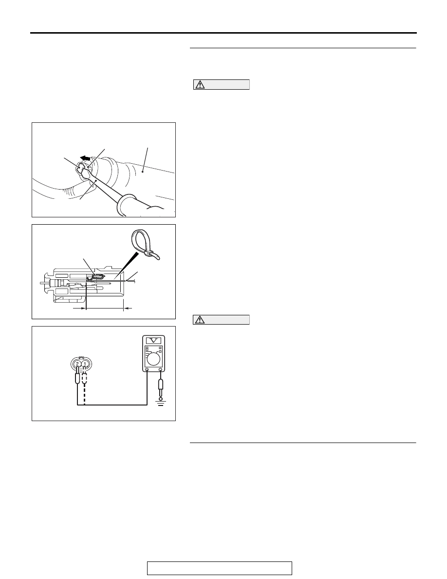
STEP 5. Voltage measurement at the D-15 intermediate 
connector.
(1) Disconnect the negative battery terminal.

DANGER

To prevent the air bag from deploying unintentionally, 
disconnect the curtain air bag module connector F-28 
to short the squib circuit.

(2) Disconnect curtain air bag module (LH) F-28. Use a 

flat-tipped screwdriver to unlock the locking button at the 
harness side connector by withdrawing it toward you in two 
stages, and then disconnect the connector.

(3) Disconnect the D-15 intermediate connector (connection 

between curtain air bag harness and floor harness).

(4) Because the short spring is installed to the D-15 

intermediate connector (curtain air bag harness side), insert 
a cable tie [3 mm (0.12 inch) wide, 0.5 mm (0.02 inch) thick] 
between terminals 1, 2 and the short spring to release the 
short spring.

(5) Connect the negative battery terminal.
(6) Ignition switch: ON

CAUTION

Do not insert a probe into the terminal from its front side 
directly, as the connector contact pressure may be weak-
ened.
(7) Check for continuity between the D-15 intermediate 

connector (curtain air bag harness side) terminal No. 1, 2 
and the body ground.
Voltage should measure 0 volt.

Q: Is the measured voltage 0 volt?

YES : Replace the curtain air bag module (squib) (Refer to 

P.52B-409

). 

NO :  Repair the wiring harness.

STEP 6. Recheck for diagnostic trouble code. 
Check again if the DTC is set.
(1) Erase the DTC.
(2) Turn the ignition switch to the "ON" position.
(3) Check if the DTC is set.
(4) Turn the ignition switch to the "LOCK" (OFF) position.
Q: Is DTC B1B19 set?

YES : Replace SRS-ECU (Refer to 

P.52B-383

).

NO :  Intermittent Malfunction (Refer to GROUP 00, How to 

Use Troubleshooting/Inspection Service Points 

− How 

to Cope with Intermittent Malfunction 

P.00-15

).

AC609928AB

Locking 
button

Flat-tipped 
screwdriver

Inflator

Curtain air bag wiring 
harness connector

AC700119

D-15 Intermediate 
connector (module side ) 

22 mm or more

Cable tie

Short spring

AH

AC608813BF

D-15 Intermediate connector 
(Curtain air bag harness side)
(rear view)

SRS AIR BAG DIAGNOSIS

TSB Revision

SUPPLEMENTAL RESTRAINT SYSTEM (SRS)

52B-128

DTC B1B1A: Curtain Air Bag Module (LH) (Squib) System (Squib Circuit Open)

CURTAIN AIR BAG 
MODULE (SQUIB) (LH)

CONNECTOR
LOCK 
SWITCH

CONNECTOR
LOCK 
SWITCH

SRS-ECU

NOTE

: CONNECTOR COUPLED : ON

CONNECTOR UNCOUPLED : OFF

Curtain Air Bag Module (Squib) (LH) Circuit

CONNECTOR
LOCK SWITCH

AC708951AD

Connector: C-36

C-36 (Y)

AC708955AB

Connector: D-15

D-15 (Y)

SRS AIR BAG DIAGNOSIS

TSB Revision

SUPPLEMENTAL RESTRAINT SYSTEM (SRS)

52B-129

CAUTION

If DTC B1B1A is set in the SRS-ECU, always diag-
nose the CAN main bus line.

.

CIRCUIT OPERATION

• The SRS-ECU judges how severe a collision is 

by detecting signals from the side impact sensors 
installed on the lower side of the center pillar. If 
the impact is over a predetermined level, the 
SRS-ECU sends an ignition signal. At this time, if 
the side collision safing G-sensor is on, the SRS 
air bag will inflate. 

• The ignition signal is input to the curtain air bag 

module (LH) to inflate the curtain air bag.

.

DTC SET CONDITIONS

This DTC is set if there is abnormal resistance 
between the input terminals of the curtain air bag 
module (LH) (squib).

.

TROUBLESHOOTING HITS

• Open circuit in the curtain air bag module (LH) 

(squib) circuit

• Improper connector contact

• Malfunction of the SRS-ECU

DIAGNOSIS

Required Special Tools:

• MB991958: Scan Tool (M.U.T.-III Sub Assembly)

• MB991824: Vehicle Communication Interface (V.C.I.)

• MB991827: M.U.T.-III USB Cable

• MB991910: M.U.T.-III Main Harness A (Vehicles with 

CAN Communication System)

• MB991865: Dummy resistor

• MB991866: Resister harness

• MB991884: Resister harness

AC708970AB

Connector: F-28

F-28 (B)

SRS AIR BAG DIAGNOSIS

TSB Revision

SUPPLEMENTAL RESTRAINT SYSTEM (SRS)

52B-130

STEP 1. Using scan tool MB991958, diagnose the CAN bus 
line.

CAUTION

To prevent damage to scan tool MB991958, always turn the 
ignition switch to the "LOCK" (OFF) position before con-
necting or disconnecting scan tool MB991958.
(1) Connect scan tool MB991958. Refer to "How to connect the 

scan tool 

P.52B-28

."

(2) Turn the ignition switch to the "ON" position.
(3) Diagnose the CAN bus line.
(4) Turn the ignition switch to the "LOCK" (OFF) position.
Q: Is the CAN bus line found to be normal?

YES : Go to Step 2.
NO :  Repair the CAN bus line (Refer to GROUP 54C, 

Diagnosis 

P.54C-14

).

STEP 2. Recheck for diagnostic trouble code.
Check again if the DTC is set.
(1) Erase the DTC.
(2) Turn the ignition switch to "ON" position.
(3) Check if the DTC is set.
(4) Turn the ignition switch to the "LOCK" (OFF) position.
Q: Is the DTC set?

YES : Go to Step 3.
NO :  There is an intermittent malfunction such as poor 

engaged connector(s) or open circuit (Refer to 
GROUP 00, How to Use Troubleshooting/Inspection 
Service Points 

− How to Cope with Intermittent 

Malfunctions 

P.00-15

).

AC608435

Data link connector

MB991827

MB991824

MB991910

AB


Content   ..  668  669  670  671   ..