Mitsubishi Evolution X. Manual - part 669


  Index      Mitsubishi     Mitsubishi Evolution X - service repair manual 2008 year


Search            


Content   ..  667  668  669  670   ..


Mitsubishi Evolution X. Manual - part 669


SRS AIR BAG DIAGNOSIS

TSB Revision

SUPPLEMENTAL RESTRAINT SYSTEM (SRS)

52B-123

CAUTION

If DTC B1B19 is set in the SRS-ECU, always diag-
nose the CAN main bus line.

.

CIRCUIT OPERATION

• The SRS-ECU judges how severe a collision is 

by detecting signals from the side impact sensors 
installed on the lower side of the center pillar. If 
the impact is over a predetermined level, the 
SRS-ECU sends an ignition signal. At this time, if 
the side collision safing G-sensor is on, the SRS 
air bag will inflate. 

• The ignition signal is input to the curtain air bag 

module (LH) to inflate the curtain air bag.

.

DTC SET CONDITIONS

This DTC is set if there is abnormal resistance 
between the input terminals of the curtain air bag 
module (LH) (squib).

.

TROUBLESHOOTING HITS

• Damaged wiring harnesses or connectors

• Short to the power supply in the curtain air bag 

module (LH) (squib) harness

• Malfunction of the SRS-ECU

DIAGNOSIS

Required Special Tools:

• MB991958: Scan Tool (M.U.T.-III Sub Assembly)

• MB991824: Vehicle Communication Interface (V.C.I.)

• MB991827: M.U.T.-III USB Cable

• MB991910: M.U.T.-III Main Harness A (Vehicles with 

CAN Communication System)

• MB991865: Dummy resistor

• MB991866: Resister harness
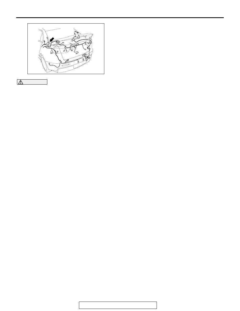
AC708970AB

Connector: F-28

F-28 (B)

SRS AIR BAG DIAGNOSIS

TSB Revision

SUPPLEMENTAL RESTRAINT SYSTEM (SRS)

52B-124

STEP 1. Using scan tool MB991958, diagnose the CAN bus 
line.

CAUTION

To prevent damage to scan tool MB991958, always turn the 
ignition switch to the "LOCK" (OFF) position before con-
necting or disconnecting scan tool MB991958.
(1) Connect scan tool MB991958. Refer to "How to connect the 

scan tool 

P.52B-28

."

(2) Turn the ignition switch to the "ON" position.
(3) Diagnose the CAN bus line.
(4) Turn the ignition switch to the "LOCK" (OFF) position.
Q: Is the CAN bus line found to be normal?

YES : Go to Step 2.
NO :  Repair the CAN bus line (Refer to GROUP 54C, 

Diagnosis 

P.54C-14

).

STEP 2. Recheck for diagnostic trouble code.
Check again if the DTC is set.
(1) Erase the DTC.
(2) Turn the ignition switch to "ON" position.
(3) Check if the DTC is set.
(4) Turn the ignition switch to the "LOCK" (OFF) position.
Q: Is the DTC set?

YES : Go to Step 3.
NO :  There is an intermittent malfunction such as poor 

engaged connector(s) or open circuit (Refer to 
GROUP 00, How to Use Troubleshooting/Inspection 
Service Points 

− How to Cope with Intermittent 

Malfunctions 

P.00-15

).

AC608435

Data link connector

MB991827

MB991824

MB991910

AB

SRS AIR BAG DIAGNOSIS

TSB Revision

SUPPLEMENTAL RESTRAINT SYSTEM (SRS)

52B-125

STEP 3. Check by dummy resistor connection.
(1) Disconnect the negative battery terminal.
(2) Disconnect the D-15 intermediate connector (connection 

between curtain air bag harness and floor harness).

(3) Connect special tool MB991865 to special tool MB991866.

CAUTION

Do not insert a probe into the terminal from its front side 
directly, as the connector contact pressure may be weak-
ened.
(4) Insert the probe of resistor harness, to which the dummy 

resistor is installed, from the back of D-15 intermediate 
connector (floor harness side).

(5) Connect the negative battery terminal.
(6) After erasing the diagnostic trouble code memory, check the 

diagnostic trouble code again.

(7) Disconnect the negative battery terminal.
Q: Is DTC B1B19 set?

YES : Go to Step 4.
NO :  Go to Step 5.

AC507310

D-15 Intermediate connector
(Curtain air bag harness side)

D-15 
Intermediate 
connector 
(Floor harness side)

AV

MB991865
(Dummy resistor: 3    )

MB991866 

(Resistor harness)

SRS AIR BAG DIAGNOSIS

TSB Revision

SUPPLEMENTAL RESTRAINT SYSTEM (SRS)

52B-126

STEP 4. Voltage measurement at the C-36 SRS-ECU 
connector. 
(1) Disconnect the negative battery terminal.
(2) While pushing the part "A" indicated in the figure of the 

harness side connector, turn the lock lever to the direction 
of the arrow to release the lock lever, and disconnect the 
C-36 SRS-ECU connector.

DANGER

To prevent the air bag from deploying unintentionally, 
disconnect the intermediate connector D-15 to short 
the squib circuit.

(3) Disconnect the D-15 intermediate connector (connection 

between curtain air bag harness and floor harness).

CAUTION

The short spring may not be released due to the insuffi-
cient insertion. Therefore, insert the insulator for 4 mm (0.6 
inch) or more.
(4) Insert a cable tie [3 mm (0.12 inch) wide, 0.5 mm (0.02 inch) 

thick] between terminal 41, 42 and the short spring to 
release the short spring.

(5) Connect the negative battery terminal.
(6) Ignition switch: ON

(7) Measure the voltage between the C-36 wiring harness side 

connector terminal No. 41, 42 and body ground.
Voltage should measure 0 volt

Q: Is the measured 0 volt?

YES : Go to Step 6.
NO :  Repair the wiring harness.

AC507645

A

AC

Lock lever

AC507303 BY

A

A

C-36 Harness side
connector (front view)

Section
A - A

Cable tie

Short spring

4 mm (0.16 inch) or more

Terminal

AC608813

C-36 Harness side 
connector (front view)

BE


Content   ..  667  668  669  670   ..