Mitsubishi Evolution X. Manual - part 665


  Index      Mitsubishi     Mitsubishi Evolution X - service repair manual 2008 year


Search            


Content   ..  663  664  665  666   ..


Mitsubishi Evolution X. Manual - part 665


SRS AIR BAG DIAGNOSIS

TSB Revision

SUPPLEMENTAL RESTRAINT SYSTEM (SRS)

52B-107

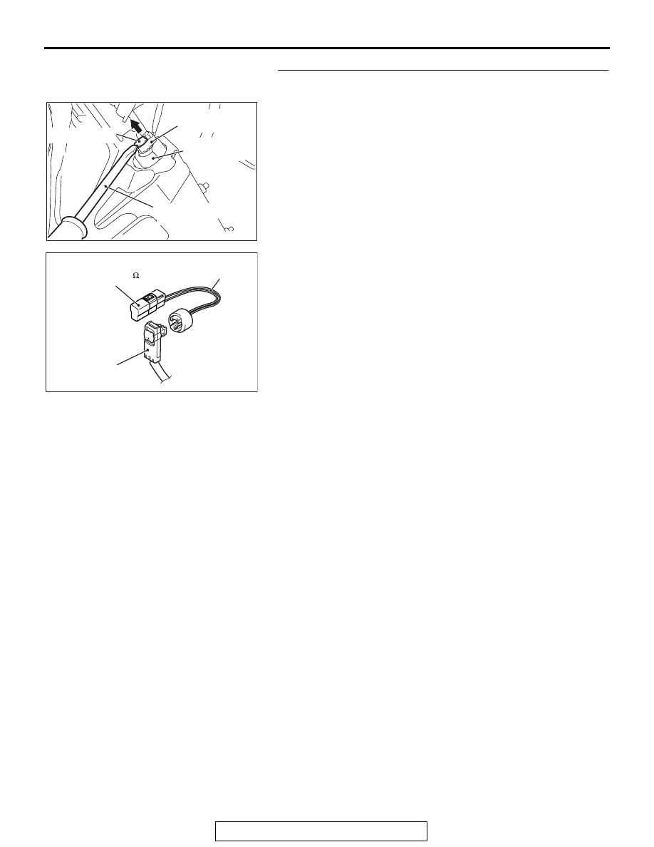
STEP 3. Check the knee air bag module.
(1) Disconnect the negative battery terminal.
(2) Disconnect knee air bag module connector C-39. Use a 

flat-tipped screwdriver to unlock the locking button at the 
harness side connector by withdrawing it toward you in two 
stages, and then disconnect the connector.

(3) Connect special tool MB991865 to special tool MB991884.
(4) Connect special tool MB991884 to the C-39 harness side 

connector.

(5) Connect the negative battery terminal.
(6) Erase diagnostic trouble code memory, and then check the 

diagnostic trouble code.

Q: Is DTC B1B12 set?

YES : Go to Step 4.
NO :  Replace the driver's knee air bag module (Refer to 

P.52B-398

). Then go to Step 5. 

AC609126AC

Locking button

Flat-tipped
screwdriver

Pre-tensioner

Harness side
connector

AC301553CA

C-39 Harness side 
connector

MB991884 

(Resistor harness)

MB991865

(Dummy resistor: 3    )

SRS AIR BAG DIAGNOSIS

TSB Revision

SUPPLEMENTAL RESTRAINT SYSTEM (SRS)

52B-108

STEP 4. Check the harness for open circuit between 
SRS-ECU connector C-37 (terminal No.1 and 2) and the 
knee air bag module C-39 (terminal No.2 and 1).
(1) Disconnect the negative battery terminal.
(2) While pushing the part "A" indicated in the figure of the 

harness side connector, turn the lock lever to the direction 
of the arrow to release the lock lever, and disconnect the 
C-37 SRS-ECU connector.

DANGER

To prevent the knee air bag module from deploying 
unintentionally, disconnect the knee air bag module 
connector C-39 to short the squib circuit.

(3) Disconnect SRS-ECU connector C-37 and knee air bag 

module connector C-39, and measure at the wiring harness 
side. For connector C-39, use a flat-tipped screwdriver to 
unlock the locking button at the harness side connector by 
withdrawing it toward you in two stages, and then 
disconnect the connector.

CAUTION

Insert an insulator such as a cable tie to a depth of 4mm 
(0.16 inch) or more, otherwise the short spring will not be 
released.
(4) Insert a cable tie [3 mm (0.12 inch) wide, 0.5 mm (0.02 inch) 

thick] between terminals 1, 2 and the short spring to release 
the short spring.

AC506734

A

AD

Lock lever

AC609126AC

Locking button

Flat-tipped
screwdriver

Pre-tensioner

Harness side
connector

AC507302BJ

A

A

C-37 Harness side
connector (front view)

Section
A - A

Cable tie

Short spring

4 mm (0.16 inch) or more

Terminal

SRS AIR BAG DIAGNOSIS

TSB Revision

SUPPLEMENTAL RESTRAINT SYSTEM (SRS)

52B-109

(5) Connect C-39 harness side connector to special tool 

MB991884.

(6) Check for continuity between the following terminals. It 

should be less than 2 ohms.

• SRS-ECU connector C-37 (terminal No.1) and the spe-

cial tool (terminal No.1)

• SRS-ECU connector C-37 (terminal No.2) and the spe-

cial tool (terminal No.2)

Q: Does continuity exist?

YES : Erase the diagnostic trouble code memory, and 

recheck if any DTC set. If DTC B1B12 set, replace the 
SRS-ECU (Refer to 

P.52B-383

). Then go to Step 5.

NO :  Replace harness wires between SRS-ECU connector 

C-37 and knee air bag module connector C-39. Then 
go to Step 5.

STEP 5. Recheck for diagnostic trouble code.
Check again if the DTC is set.
(1) Erase the DTC.
(2) Turn the ignition switch to the "ON" position.
(3) Check if the DTC is set.
(4) Turn the ignition switch to the "LOCK" (OFF) position.
Q: Is DTC B1B12 set?

YES : Return to Step 1. 
NO :  The procedure is complete.

AC201287EJ

C-39 Harness side 
connector

MB991884 
(Resistor harness)

AC608812FK

Resistor harness 
side connector

C-37 Harness side 
connector (front view)

SRS AIR BAG DIAGNOSIS

TSB Revision

SUPPLEMENTAL RESTRAINT SYSTEM (SRS)

52B-110

DTC B1B13: Driver's Knee Air Bag (Squib) System (Short Circuit Between Squib Circuit Terminals)

CAUTION

If DTC B1B13 is set in the SRS-ECU, always diag-
nose the CAN main bus line.

.

CIRCUIT OPERATION

The SRS-ECU judges how severe a collision is by 
detecting signals from the front impact sensors and 
the front air bag analog G-sensor. If the impact is 
over a predetermined level, the SRS-ECU sends an 
ignition signal. At this time, if the front air bag safing 
G-sensor is on, the knee air bag module will deploy. 

.

DTC SET CONDITIONS

This DTC is set if there is abnormal resistance 
between the input terminals of the knee air bag mod-
ule (squib).

.

TROUBLESHOOTING HITS

• Improper engaged connector or defective short 

spring*

• Short circuit between the knee air bag module 

(squib) circuit terminals

• Damaged connector(s)

KNEE AIR BAG
MODULE (SQUIB)

SRS-ECU

CONNECTOR LOCK SWITCH 

CONNECTOR COUPLED: ON 

CONNECTOR UNCOUPLED: OFF

NOTE

:   


Knee Air Bag Module (Squib) Circuit

AC708951AC

C-37 (Y)

Connector: C-37

AC708950AB

Connector: C-39

C-39 (B)


Content   ..  663  664  665  666   ..