Mitsubishi Evolution X. Manual - part 664


  Index      Mitsubishi     Mitsubishi Evolution X - service repair manual 2008 year


Search            


Content   ..  662  663  664  665   ..


Mitsubishi Evolution X. Manual - part 664


SRS AIR BAG DIAGNOSIS

TSB Revision

SUPPLEMENTAL RESTRAINT SYSTEM (SRS)

52B-103

STEP 4. Check the knee air bag module circuit. Measure 
the voltage at the SRS-ECU connector C-37.
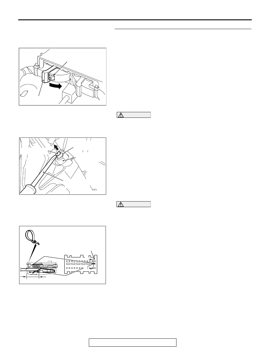
(1) Disconnect the negative battery terminal.
(2) While pushing the part "A" indicated in the figure of the 

harness side connector, turn the lock lever to the direction 
of the arrow to release the lock lever, and disconnect the 
C-37 SRS-ECU connector.

DANGER

To prevent the knee air bag module from deploying 
unintentionally, disconnect the knee air bag module 
connector C-39 to short the squib circuit.

(3) Disconnect knee air bag module connector C-39. Use a 

flat-tipped screwdriver to unlock the locking button at the 
harness side connector by withdrawing it toward you in two 
stages, and then disconnect the connector.

CAUTION

Insert an insulator such as a cable tie to a depth of 4mm 
(0.16 inch) or more, otherwise the short spring will not be 
released.
(4) Insert a cable tie [3 mm (0.12 inch) wide, 0.5 mm (0.02 inch) 

thick] between terminals 1, 2 and the short spring to release 
the short spring.

(5) Connect the negative battery terminal.
(6) Ignition switch: ON.

AC506734

A

AD

Lock lever

AC609126AC

Locking button

Flat-tipped
screwdriver

Pre-tensioner

Harness side
connector

AC507302BJ

A

A

C-37 Harness side
connector (front view)

Section
A - A

Cable tie

Short spring

4 mm (0.16 inch) or more

Terminal

SRS AIR BAG DIAGNOSIS

TSB Revision

SUPPLEMENTAL RESTRAINT SYSTEM (SRS)

52B-104

(7) Measure the voltage between C-37 harness side connector 

terminals 1, 2 and body ground.
Voltage should measure 0 volt.

Q: Is the measured voltage 0 volt?

YES : Erase the diagnostic trouble code memory, and check 

the diagnostic trouble code. If DTC B1B11 sets, 
replace the SRS-ECU (Refer to 

P.52B-383

). Then go 

to Step 6.

NO :  Go to Step 5.

STEP 5. Check the harness wires for short circuit to power 
supply between SRS-ECU connector C-37 (terminal No.1 
and 2) and knee air bag module connector C-39 (terminal 
No.2 and 1).
Q: Are the harness wires between SRS-ECU connector 

C-37 (terminal No.1 and 2) and knee air bag module 
connector C-39 (terminal No.2 and 1) in good condition?
YES : 
Go to Step 6.
NO :  Replace the harness wires between SRS-ECU 

connector C-37 and knee air bag module connector 
C-39. Then go to Step 6.

STEP 6. Recheck for diagnostic trouble code. 
Check again if the DTC is set.
(1) Erase the DTC.
(2) Turn the ignition switch to the "ON" position.
(3) Check if the DTC is set.
(4) Turn the ignition switch to the "LOCK" (OFF) position.
Q: Is DTC B1B11 set?

YES : Return to Step 1. 
NO :  The procedure is complete.

AC608813

C-37 Harness side 
connector (front view)

BD

SRS AIR BAG DIAGNOSIS

TSB Revision

SUPPLEMENTAL RESTRAINT SYSTEM (SRS)

52B-105

DTC B1B12: Driver's Knee Air Bag (Squib) System (Squib Circuit Open)

CAUTION

If DTC B1B12 is set in the SRS-ECU, always diag-
nose the CAN main bus line.

.

CIRCUIT OPERATION

The SRS-ECU judges how severe a collision is by 
detecting signals from the front impact sensors and 
the front air bag analog G-sensor. If the impact is 
over a predetermined level, the SRS-ECU sends an 
ignition signal. At this time, if the front air bag safing 
G-sensor is on, the knee air bag module will deploy. 

.

DTC SET CONDITIONS

This DTC is set if there is abnormal resistance 
between the input terminals of the knee air bag mod-
ule (squib).

.

TROUBLESHOOTING HITS

• Improper connector contact

• Open circuit in the knee air bag module (squib) 

circuit

• Malfunction of the SRS-ECU

KNEE AIR BAG
MODULE (SQUIB)

SRS-ECU

CONNECTOR LOCK SWITCH 

CONNECTOR COUPLED: ON 

CONNECTOR UNCOUPLED: OFF

NOTE

:   


Knee Air Bag Module (Squib) Circuit

AC708951AC

C-37 (Y)

Connector: C-37

AC708950AB

Connector: C-39

C-39 (B)


SRS AIR BAG DIAGNOSIS

TSB Revision

SUPPLEMENTAL RESTRAINT SYSTEM (SRS)

52B-106

DIAGNOSIS

Required Special Tools:

• MB991958: Scan Tool (M.U.T.-III Sub Assembly)

• MB991824: Vehicle Communication Interface (V.C.I.)

• MB991827: M.U.T.-III USB Cable

• MB991910: M.U.T.-III Main Harness A (Vehicles with 

CAN Communication System)

• MB991865: Dummy resistor

• MB991884: Resister harness

STEP 1. Using scan tool MB991958, diagnose the CAN bus 
line.

CAUTION

To prevent damage to scan tool MB991958, always turn the 
ignition switch to the "LOCK" (OFF) position before con-
necting or disconnecting scan tool MB991958.
(1) Connect scan tool MB991958. Refer to "How to connect the 

scan tool 

P.52B-28

."

(2) Turn the ignition switch to the "ON" position.
(3) Diagnose the CAN bus line.
(4) Turn the ignition switch to the "LOCK" (OFF) position.
Q: Is the CAN bus line found to be normal?

YES : Go to Step 2.
NO :  Repair the CAN bus line (Refer to GROUP 54C, 

Diagnosis 

P.54C-14

).

STEP 2. Recheck for diagnostic trouble code.
Check again if the DTC is set.
(1) Erase the DTC.
(2) Turn the ignition switch to the "ON" position.
(3) Check if the DTC is set.
(4) Turn the ignition switch to the "LOCK" (OFF) position.
Q: Is the DTC set?

YES : Go to Step 3.
NO :  There is an intermittent malfunction such as poor 

engaged connector(s) or open circuit (Refer to 
GROUP 00, How to Cope with Intermittent 
Malfunction 

P.00-15

).

AC608435

Data link connector

MB991827

MB991824

MB991910

AB


Content   ..  662  663  664  665   ..