Mitsubishi Evolution X. Manual - part 650


  Index      Mitsubishi     Mitsubishi Evolution X - service repair manual 2008 year


Search            


Content   ..  648  649  650  651   ..


Mitsubishi Evolution X. Manual - part 650


SRS AIR BAG DIAGNOSIS

TSB Revision

SUPPLEMENTAL RESTRAINT SYSTEM (SRS)

52B-47

STEP 5. Check the driver’s air bag module circuit. Measure 
the resistance at the SRS-ECU connector C-37.
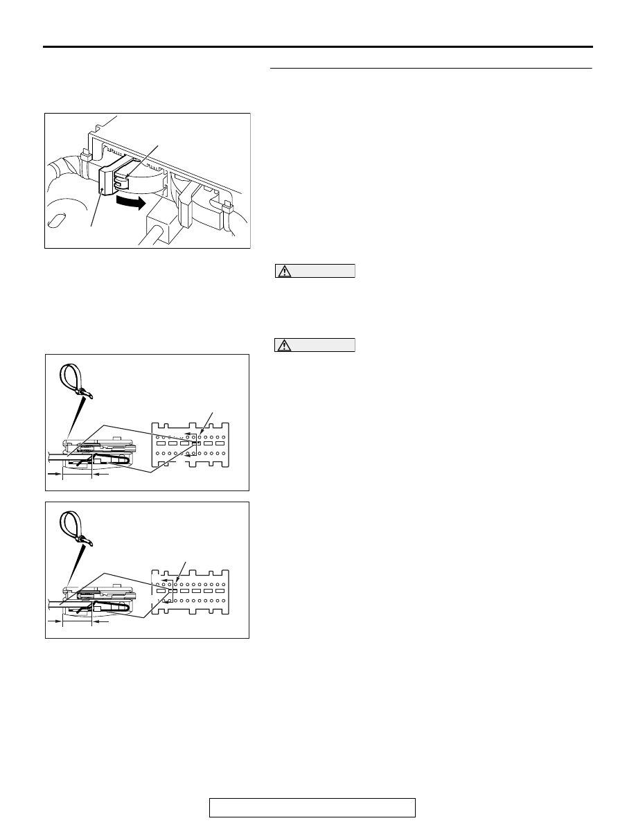
(1) Disconnect the negative battery terminal.
(2) While pushing the part "A" indicated in the figure of the 

harness side connector, turn the lock lever to the direction 
of the arrow to release the lock lever, and disconnect the 
C-37 SRS-ECU connector.

DANGER

To prevent the air bag from deploying unintentionally, 
disconnect the clock spring connector C-208 to short 
the squib circuit.

(3) Disconnect the clock spring connector C-208.

CAUTION

Insert an insulator such as a cable tie to a depth of 4mm 
(0.16 inch) or more, otherwise the short spring will not be 
released.
(4) Insert a cable tie [3 mm (0.12 inch) wide, 0.5 mm (0.02 inch) 

thick] between terminals 5, 6 <1st squib> or 9, 10 <2nd 
squib> and the short spring to release the short spring.

AC506734

A

AD

Lock lever

AC507302 BF

A

A

C-37 Harness side
connector (front view)

Section
A - A

Cable tie

Short spring

Terminal

<1st Squib>

4 mm (0.16 inch) or more

AC507302BG

A

A

<2nd Squib>

C-37 Harness side
connector (front view)

Section
A - A

Cable tie

Short spring

4 mm (0.16 inch) or more

Terminal

SRS AIR BAG DIAGNOSIS

TSB Revision

SUPPLEMENTAL RESTRAINT SYSTEM (SRS)

52B-48

(5) Check for continuity between C-37 harness side connector 

terminals 5 and 6 <1st squib> or 9 and 10 <2nd squib> and 
body ground.
It should be open circuit.

Q: Is it open circuit?

YES : Erase the diagnostic trouble code memory, and check 

the diagnostic trouble code. If DTC B1B00 <1st 
squib> or B1B04 <2nd squib> sets, replace the 
SRS-ECU (Refer to 

P.52B-383

). Then go to Step 7

NO :  Go to Step 6.

STEP 6. Check the harness for short circuit to ground 
between SRS-ECU connector C-37 (terminal No.5 and 6 
<1st squib> or terminal No.9 and 10 <2nd squib>) and 
clock spring connector C-208 (terminal No.4 and 3 <1st 
squib> or terminal No.1 and 2 <2nd squib>).
Q: Are the harness wires between SRS-ECU connector 

C-37 (terminal No.5 and 6 <1st squib> or terminal No.9 
and 10 <2nd squib>) and clock spring connector C-208 
(terminal No.4 and 3 <1st squib> or terminal No. 1 and 2 
<2nd squib>) in good condition?
YES : 
Go to Step 7.
NO :  Replace the harness wires between SRS-ECU 

connector C-37 and clock spring connector C-208. 
Then go to Step 7.

STEP 7. Recheck for diagnostic trouble code. 
Check again if the DTC is set.
(1) Erase the DTC.
(2) Turn the ignition switch to the "ON" position.
(3) Check if the DTC is set.
(4) Turn the ignition switch to the "LOCK" (OFF) position.
Q: Is DTC B1B00 <1st squib> or B1B04 <2nd squib> set?

YES : Return to Step 1.
NO :  The procedure is complete.

AC608812

C-37 Harness side 
connector (front view)

EW

<1st squib>

AC608812

C-37 Harness side 
connector (front view)

EX

<2nd  squib>

SRS AIR BAG DIAGNOSIS

TSB Revision

SUPPLEMENTAL RESTRAINT SYSTEM (SRS)

52B-49

DTC B1B01: Driver's Air bag Module (1st squib) System (Shorted to Squib Circuit Power Supply)


DTC B1B05: Driver's Air bag Module (2nd squib) System (Shorted to Squib Circuit Power Supply 

CAUTION

If DTC B1B01 <1st squib> or B1B05 <2nd squib> 
is set in the SRS-ECU, always diagnose the CAN 
main bus line.

.

SRS-ECU

CLOCK
SPRING

DRIVER'S AIR BAG
MODULE (SQUIB)

CONNECTOR LOCK SWITCH 

CONNECTOR COUPLED: ON 

CONNECTOR UNCOUPLED: OFF

NOTE

:   


Driver's Air Bag Module (Squib) Circuit

AC708951AC

C-37 (Y)

Connector: C-37

AC708953AB

Connectors: C-204, C-208

C-208 (Y)

C-204 (Y)

SRS AIR BAG DIAGNOSIS

TSB Revision

SUPPLEMENTAL RESTRAINT SYSTEM (SRS)

52B-50

CIRCUIT OPERATION

• The SRS-ECU judges how severe a collision is 

by detecting signals from the front impact sensors 
and the front air bag analog G-sensor. If the 
impact is over a predetermined level, the 
SRS-ECU sends an ignition signal. At this time, if 
the front air bag safing G-sensor is on, the SRS 
air bag will inflate. 

• The ignition signal is input to the air bag module 

via the clock spring to inflate the air bag.

.

DTC SET CONDITIONS

This DTC is set if there is abnormal resistance 
between the input terminals of the driver's air bag 
module (squib).

.

TROUBLESHOOTING HINTS

• Malfunction of the clock spring

• Damaged harness wires and connectors

• Short to the power supply in the driver's air bag 

module (squib) harness

• Malfunction of the SRS-ECU

DIAGNOSIS

Required Special Tools:

• MB991958: Scan Tool (M.U.T.-III Sub Assembly)

• MB991824: Vehicle Communication Interface (V.C.I.)

• MB991827: M.U.T.-III USB Cable

• MB991910: M.U.T.-III Main Harness A (Vehicles with 

CAN Communication System)

• MB991865: Dummy resistor

• MB991866: Resister harness

STEP 1. Using scan tool MB991958, diagnose the CAN bus 
line.

CAUTION

To prevent damage to scan tool MB991958, always turn the 
ignition switch to the "LOCK" (OFF) position before con-
necting or disconnecting scan tool MB991958.
(1) Connect scan tool MB991958. Refer to "How to connect the 

scan tool 

P.52B-28

."

(2) Turn the ignition switch to the "ON" position.
(3) Diagnose the CAN bus line.
(4) Turn the ignition switch to the "LOCK" (OFF) position.
Q: Is the CAN bus line found to be normal?

YES : Go to Step 2.
NO :  Repair the CAN bus line (Refer to GROUP 54C, 

Diagnosis 

P.54C-14

).

AC608435

Data link connector

MB991827

MB991824

MB991910

AB


Content   ..  648  649  650  651   ..