Mitsubishi Evolution X. Manual - part 620


  Index      Mitsubishi     Mitsubishi Evolution X - service repair manual 2008 year


Search            


Content   ..  618  619  620  621   ..


Mitsubishi Evolution X. Manual - part 620


DIAGNOSIS

TSB Revision

WIRELESS CONTROL MODULE (WCM)

42C-97

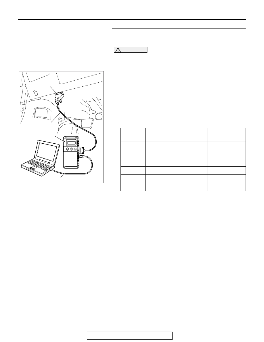
STEP 5. Using scan tool MB991958, check data list.
Check the signals related to the keyless entry system opera-
tion.

CAUTION

To prevent damage to scan tool MB991958, always turn the 
ignition switch to the "LOCK" (OFF) position before con-
necting or disconnecting scan tool MB991958.
(1) Connect scan tool MB991958. Refer to "How to connect the 

Scan Tool (M.U.T.-III) 

P.42C-6

."

(2) Turn the ignition switch to the "LOCK" (OFF) position.
(3) Check the ETACS data list.

• Close the driver's door.

• Close the passenger's door.

• Close the RH-side rear door.

• Close the LH-side rear door.

• Close the trunk lid.

• Remove the ignition key from the ignition key cylinder.

OK: Normal condition are displayed.

Item No.

Item name

Normal 
condition

Item 256

Dr door ajar switch

Close

Item 257

As door ajar switch

Close

Item 258

RR door ajar switch

Close

Item 259

RL door ajar switch

Close

Item 260

Trunk/gate trunk ajar switch Close

Item 264

Handle lock switch

Key in 

→ Key out

AC608435

Data link connector

MB991827

MB991824

MB991910

AB

DIAGNOSIS

TSB Revision

WIRELESS CONTROL MODULE (WCM)

42C-98

Q: Are the check result normal?

YES <Normal conditions are displayed for all the 
items.> : 
Go to Step 6.
NO <Normal condition is not displayed for item No. 
256.> : 
Refer to GROUP 54A, Inspection Procedure 5: 

ETACS-ECU does not receive any signal from the 
front door switch (LH) 

P.54A-656

.

NO <Normal condition is not displayed for item No. 
257.> : 
Refer to GROUP 54A, Inspection Procedure 6: 

ETACS-ECU does not receive any signal from the 
front door switch (RH) 

P.54A-654

.

NO <Normal condition is not displayed for item No. 
258.> : 
Refer to GROUP 54A, Inspection Procedure 8: 

ETACS-ECU does not receive any signal from the 
rear door switch (RH) 

P.54A-661

.

NO <Normal condition is not displayed for item No. 
260.> : 
Refer to GROUP 54A, Inspection Procedure 9: 

ETACS-ECU does not receive any signal from the 
trunk lid latch. 

P.54A-663

.

NO <Normal condition is not displayed for item No. 
264.> : 
Refer to GROUP 54A, Inspection Procedure 3: 

ETACS-ECU does not receive any signal from the key 
reminder switch. 

P.54A-644

.

STEP 6. Using scan tool MB991958, check pulse check.
Check the signals related to the keyless entry system opera-
tion.

CAUTION

To prevent damage to scan tool MB991958, always turn the 
ignition switch to the "LOCK" (OFF) position before con-
necting or disconnecting scan tool MB991958.
(1) Connect scan tool MB991958. Refer to "How to connect the 

Scan Tool (M.U.T.-III) 

P.42C-6

."

(2) Confirm the ETACS pulse check.

• Remove the ignition key from the ignition key cylinder.

OK: The scan tool (M.U.T.-III) tone alarm sounds.

Q: Is the check result normal?

YES : Go to Step 7.
NO :  Refer to "Signals from transmitter switches are not 

received 

P.42C-111

."

Item name

Conditions

Transmitter switch

Turn the switch ON/OFF.

AC608435

Data link connector

MB991827

MB991824

MB991910

AB

DIAGNOSIS

TSB Revision

WIRELESS CONTROL MODULE (WCM)

42C-99

STEP 7. Check receiver antenna assembly connector D-14 
and WCM connector C-07 for loose, corroded or damaged 
terminals, or terminals pushed back in the connector.
Q: Is the receiver antenna assembly connector D-14 and 

WCM connector C-07 in good condition?
YES : 
Go to Step 8.
NO :  Repair the defective connector.

DIAGNOSIS

TSB Revision

WIRELESS CONTROL MODULE (WCM)

42C-100

STEP 8. Check the wiring harness between the receiver 
antenna assembly connector D-14 (terminal Nos. 1, 3 and 
5) and the WCM connector C-07 (terminal Nos. 1, 3 and 5) 
for open circuit.
(1) Disconnect receiver antenna assembly connector D-14 and 

WCM connector C-07, and check the wiring harness.

(2) Check the wiring harness between receiver antenna 

assembly connector D-14 (terminal No.1) and WCM 
connector C-07 (terminal No.1).

OK: Continuity exists (2 

 or less)

(3) Check the wiring harness between receiver antenna 

assembly connector D-14 (terminal No.3) and WCM 
connector C-07 (terminal No.3).

OK: Continuity exists (2 

 or less)

(4) Check the wiring harness between receiver antenna 

assembly connector D-14 (terminal No.5) and WCM 
connector C-07 (terminal No.5).

OK: Continuity exists (2 

 or less)

Q: Is the wiring harness between receiver antenna 

assembly connector D-14 (terminal Nos. 1, 3 and 5) and 
the WCM connector C-07 (terminal Nos. 1, 3 and 5) in 
good condition?
YES  : 
Go to Step 9.
NO (receiver antenna assembly connector D-14 terminal 
No.1 

 WCM connector C-07 terminal No.1.) : Repair the 

wiring harness between receiver antenna assembly 
connector D-14 (terminal No.1) and WCM connector 
C-07 (terminal No.1).

NO (receiver antenna assembly connector D-14 terminal 
No.3 

 WCM connector C-07 terminal No.3.) : Repair the 

wiring harness between receiver antenna assembly 
connector D-14 (terminal No.3) and WCM connector 
C-07 (terminal No.3).

NO (receiver antenna assembly connector D-14 terminal 
No.5 

 WCM connector C-07 terminal No.5.) : Repair the 

wiring harness between receiver antenna assembly 
connector D-14 (terminal No.5) and WCM connector 
C-07 (terminal No.5).

AC709707HW

Harness side: D-14

Harness side: C-07

AC709707 HX

Harness side: D-14

Harness side: C-07

AC709707HY

Harness side: D-14

Harness side: C-07


Content   ..  618  619  620  621   ..