Mitsubishi Evolution X. Manual - part 542


  Index      Mitsubishi     Mitsubishi Evolution X - service repair manual 2008 year


Search            


Content   ..  540  541  542  543   ..


Mitsubishi Evolution X. Manual - part 542


DIAGNOSIS

TSB Revision

KEYLESS OPERATION SYSTEM (KOS)

42B-75

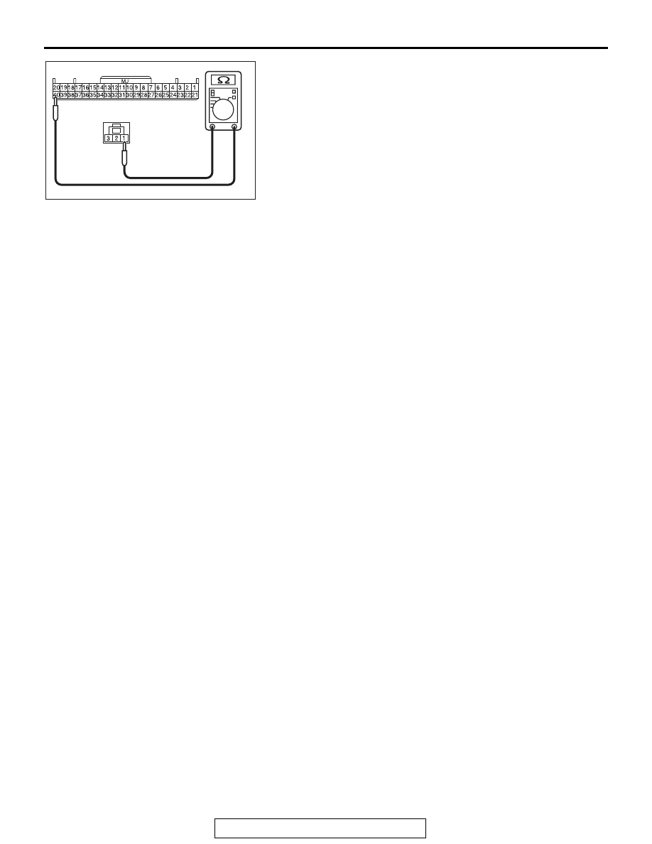
(4) Check the wiring harness between KOS-ECU connector 

C-05 (terminal No.40) and outside transmitter antenna 
assembly (driver's side) connector D-23 (terminal No.1).

OK: Continuity exists (2 

 or less)

Q: Is the wiring harness between KOS-ECU connector C-05 

(terminal Nos. 6, 17, 40) and outside transmitter antenna 
assembly (driver's side) connector D-23 (terminal Nos. 
3, 2, 1) in good condition?
YES  : 
Go to Step 3.
NO [KOS-ECU connector C-05 terminal No.6 

 outside 

transmitter antenna assembly (driver's side) connector 
D-23 terminal No.3.] : 
Repair the wiring harness between 

KOS-ECU connector C-05 (terminal No.6) and 
outside transmitter antenna assembly (driver's side) 
connector D-23 (terminal No.3).

NO [KOS-ECU connector C-05 terminal No.17 

 outside 

transmitter antenna assembly (driver's side) connector 
D-23 terminal No.2.] : 
Repair the wiring harness between 

KOS-ECU connector C-05 (terminal No.17) and 
outside transmitter antenna assembly (driver's side) 
connector D-23 (terminal No.2).

NO [KOS-ECU connector C-05 terminal No.40 

 outside 

transmitter antenna assembly (driver's side) connector 
D-23 terminal No.1.] : 
Repair the wiring harness between 

KOS-ECU connector C-05 (terminal No.40) and 
outside transmitter antenna assembly (driver's side) 
connector D-23 (terminal No.1).

AC709707EV

Harness side: D-23

Harness side: C-05

DIAGNOSIS

TSB Revision

KEYLESS OPERATION SYSTEM (KOS)

42B-76

STEP 3. Check the wiring harness between the outside 
transmitter antenna assembly (driver's side) connector 
D-23 (terminal Nos. 3, 2, 1) and the ground for short circuit.
(1) Disconnect outside transmitter antenna assembly (driver's 

side) connector D-23, and check the wiring harness.

(2) Check the wiring harness between outside transmitter 

antenna assembly (driver's side) connector D-23 (terminal 
No.3) and ground

OK: No continuity

(3) Check the wiring harness between outside transmitter 

antenna assembly (driver's side) connector D-23 (terminal 
No.2) and ground

OK: No continuity

(4) Check the wiring harness between outside transmitter 

antenna assembly (driver's side) connector D-23 (terminal 
No.1) and ground

OK: No continuity

Q: Is the wiring harness between outside transmitter 

antenna assembly (driver's side) connector D-23 
(terminal Nos. 3, 2, 1) and the ground in good 
condition?
YES  : 
Go to Step 4.
NO [outside transmitter antenna assembly (driver's 
side) connector D-23 terminal No.3 

 ground.] : Repair 

the wiring harness between outside transmitter 
antenna assembly (driver's side) connector D-23 
(terminal No.3) and ground.

NO [outside transmitter antenna assembly (driver's 
side) connector D-23 terminal No.2 

 ground.] : Repair 

the wiring harness between outside transmitter 
antenna assembly (driver's side) connector D-23 
(terminal No.2) and the ground.

NO [outside transmitter antenna assembly (driver's 
side) connector D-23 terminal No.1 

 ground.] : Repair 

the wiring harness between outside transmitter 
antenna assembly (driver's side) connector D-23 
(terminal No.1) and the ground.

AC709707IC

Harness side: D-23

AC709707ID

Harness side: D-23

AC709707IE

Harness side: D-23

DIAGNOSIS

TSB Revision

KEYLESS OPERATION SYSTEM (KOS)

42B-77

STEP 4. Keyless operation system communication test
Check that the communication with the outside transmitter 
antenna assembly (driver's side) is normal (Refer to Antenna 
Test 

P.42B-275

).

Antennas to be checked

• Driver side antenna (exterior)

OK: Normal is displayed.

Q: Is the check result normal?

YES : Go to Step 5.
NO :  Replace the outside transmitter antenna assembly 

(driver's side).

STEP 5. Check whether the diagnostic trouble code is 
reset.
(1) Erase the DTC.
(2) Turn the ignition switch from the LOCK (OFF) position to the 

ON position.

(3) Check if the DTC is set.
Q: Is the DTC set?

YES : Replace KOS-ECU and register the ID codes (Refer 

to 

P.42B-12

).

NO :  Intermittent malfunction is suspected (Refer to 

GROUP 00 

− How to Use Troubleshooting/Inspection 

Service Points 

− How to Deal with Intermittent 

Malfunction 

P.00-15

).

DIAGNOSIS

TSB Revision

KEYLESS OPERATION SYSTEM (KOS)

42B-78

DTC B240B: FL antenna(outdoor) open 

CAUTION

When replacing the ECU, always check that the 
communication circuit is normal.

AC609049

KOS-ECU

KEYLESS 
OPERATION 
KEY

OUTSIDE TRANSMISSION 
ANTENNA ASSEMBLY 
(PASSENGER'S SIDE)

SKY  BLUE

SKY  BLUE

SKY  BLUE

RED- BLA

CK

RED- BLA

CK

RED- BLA

CK

 Outside Transmission Antenna assembly (Passenger's Side) Circuit

AC

YELLO

W

YELLO

W

YELLO

W

YELLO

W

AC708950AW

C-42

Connectors: C-05, C-42

C-05

AC708951AZ

Connector: C-23


Content   ..  540  541  542  543   ..