Mitsubishi Evolution X. Manual - part 463


  Index      Mitsubishi     Mitsubishi Evolution X - service repair manual 2008 year


Search            


Content   ..  461  462  463  464   ..


Mitsubishi Evolution X. Manual - part 463


DIAGNOSIS <SHIFT LEVER>

TSB Revision

TWIN CLUTCH- SPORTRONIC SHIFT TRANSMISSION (TC-SST)

22C-309

SYMPTOM PROCEDURES

INSPECTION PROCEDURE 1: The scan tool cannot communicate with the shift lever-ECU.

CAUTION

Whenever the ECU is replaced, ensure that the 
CAN bus lines are normal.

.

COMMENTS ON TROUBLE SYMPTOM

The CAN bus line, shift lever-ECU power supply cir-
cuit, or shift lever-ECU may have a problem.

.

PROBABLE CAUSES

• Wrong M.U.T.-III wiring harness

• The CAN bus line is defective.

• Malfunction of the shift lever-ECU power supply 

circuit

• Malfunction of the shift lever-ECU

• ECU malfunction of other system

STEP 1. Scan tool CAN bus diagnostics
Using scan tool MB991958, diagnose the CAN bus lines.
Q: Is the check result normal?

YES : Check and repair the shift lever-ECU power supply 

circuit. (Refer to 

P.22C-319

.)

NO :  Repair the CAN bus lines. (Refer to GROUP 54C 

− 

Troubleshooting 

P.54C-14

.)

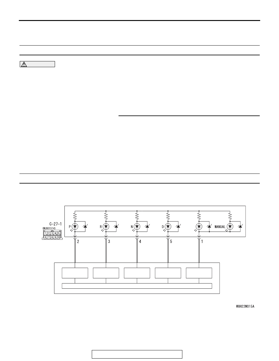
INSPECTION PROCEDURE 2: Shift indicator light does not illuminate.

CPU

LOW SIDE 
SWITCH

LOW SIDE 
SWITCH

LOW SIDE 
SWITCH

LOW SIDE 
SWITCH

LOW SIDE 
SWITCH

SHIFT LEVER 
POSITION 
INDICATOR 
PANEL

SHIFT 
LEVER

Shift lever position indicator panel circuit

DIAGNOSIS <SHIFT LEVER>

TSB Revision

TWIN CLUTCH- SPORTRONIC SHIFT TRANSMISSION (TC-SST)

22C-310

CAUTION

Whenever the ECU is replaced, ensure that the 
CAN bus lines are normal.

.

COMMENTS ON TROUBLE SYMPTOM

The shift indicator light or shift lever-ECU may have a 
problem.

.

PROBABLE CAUSES

• Malfunction of the shift indicator light

• Damaged harness wires and connectors

• Malfunction of the shift lever-ECU

DIAGNOSTIC PROCEDURE

STEP 1. Scan tool CAN bus diagnostics
Using scan tool MB991958, diagnose the CAN bus lines.
Q: Is the check result normal?

YES : Go to Step 2.
NO :  Repair the CAN bus lines. (Refer to GROUP 54C 

− 

Troubleshooting 

P.54C-14

.) After repairing the CAN 

bus line, go to Step 2.

STEP 2. Scan tool service data
Item No. 1: Shift lever position (Refer to Service Data Refer-
ence Table 

P.22C-322

.)

Q: Is the check result normal?

YES : Go to Step 3.
NO :  Replace the shift lever assembly. (Refer to 

P.22C-334

.)

STEP 3. Scan tool actuator test
Item No. 1: Shift indicator (Refer to Special Function (Actuator 
Test Reference Table 

P.22C-325

.)

Q: Is the check result normal?

YES : Intermittent malfunction. (Refer to GROUP 00 

− How 

to Cope with Intermittent Malfunction 

P.00-15

.)

NO :  Go to Step 4.

AC705170AN

Connector: C-27-1

DIAGNOSIS <SHIFT LEVER>

TSB Revision

TWIN CLUTCH- SPORTRONIC SHIFT TRANSMISSION (TC-SST)

22C-311

STEP 4. Inspection of the floor console panel assembly 
connector: C-27-1
Check for the contact with terminals.
Q: Is the check result normal?

YES : Replace the floor console panel assembly. (Refer to 

GROUP 52A 

− Floor Console Assembly 

P.52A-9

.)

NO :  Repair the defective connector.

DIAGNOSIS <SHIFT LEVER>

TSB Revision

TWIN CLUTCH- SPORTRONIC SHIFT TRANSMISSION (TC-SST)

22C-312

INSPECTION PROCEDURE 3: Back-up light does not illuminate.

IGNITION
SWITCH (IG1)

ETACS-ECU

IG1
RELAY

CPU

SHIFT LEVER

SHIFT LEVER
POSITION
SENSOR (R)

HIGH SIDE
SWITCH (R)

BACKUP
LIGHT

(LH)

(RH)

JOINT
CONNECTOR 
(4)

JOINT
CONNECTOR 
(4)

FUSIBLE 
LINK

34

Backup lamp switch system circuit


Content   ..  461  462  463  464   ..