Mitsubishi Evolution X. Manual - part 456
DIAGNOSIS <TC-SST>
TSB Revision
TWIN CLUTCH- SPORTRONIC SHIFT TRANSMISSION (TC-SST)
22C-281
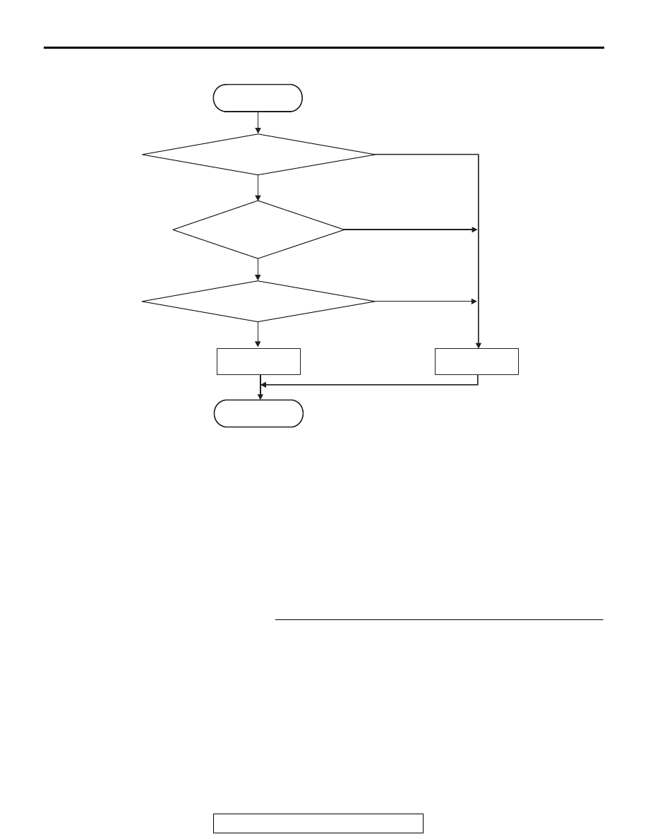
LOGIC FLOW CHARTS (Monitor Sequence)
.
DTC SET CONDITIONS
Check Conditions
• Voltage of battery: 8 V or more.
• Voltage of battery: 16.5 V or less.
• Clutch / shift changeover solenoid 2: ON.
JUDGMENT CRITERIA
• FET (Field Effect Transistor) output: (Battery volt-
age
− 2 V) or more. (160 millisecond)
.
OBD-II DRIVE CYCLE PATTERN
The FET channel output remains (Battery voltage
− 2
V) or less for 160 milliseconds.
.
PROBABLE CAUSES
• Malfunction of TC-SST-ECU
DIAGNOSTIC PROCEDURE
STEP 1. Scan tool CAN bus diagnostics
Using scan tool MB991958, diagnose the CAN bus lines.
Q: Is the check result normal?
YES : Go to Step 2.
NO : Repair the CAN bus lines. (Refer to GROUP 54C
−
Troubleshooting
.) After repairing the CAN
bus line, go to Step 2.
AC710667
START
No
Good
Malfunction
END
Monitoring condition met
Continuous failure
for 160 msec
No
Yes
Yes
Yes
No
FET* output
> Battery voltage - 2 V
*FET : Field Effect Transistor