Mitsubishi Evolution X. Manual - part 433
DIAGNOSIS <TC-SST>
TSB Revision
TWIN CLUTCH- SPORTRONIC SHIFT TRANSMISSION (TC-SST)
22C-189
STEP 2. Check whether the DTC is reset.
Q: Is DTC No. P1858 set?
YES : Replace the TC-SST assembly. (Refer to
NO : Intermittent malfunction. (Refer to GROUP 00
− How
to Cope with Intermittent Malfunction
.)
DTC P1859: Disengagement too late with clutch 1
CAUTION
• If there is any problem in the CAN bus lines,
an incorrect diagnostic trouble code may be
set. Prior to this diagnosis, diagnose the CAN
bus lines.
• Whenever the ECU is replaced, ensure that
the CAN bus lines are normal.
.
DIAGNOSTIC FUNCTION
TC-SST-ECU checks that the clutch 1 is normal.
.
DESCRIPTIONS OF MONITOR METHODS
The disengagement of the clutch 1 is determined to
be late.
.
MONITOR EXECUTION
• Continuous
.
MONITOR EXECUTION CONDITIONS
(OTHER MONITOR AND SENSOR)
Other Monitor (There is no temporary DTC stored
in memory for the item monitored below)
• P0841: Clutch 1 pressure sensor system (Poor
performance)
• P0842: Clutch 1 pressure sensor system (Output
low range out)
• P0843: Clutch 1 pressure sensor system (Output
high range out)
• P1836: Shift fork 1 malfunction
• P183D: Shift fork 2 malfunction
Sensor (The sensor below is determined to be
normal)
• Clutch 1 pressure sensor
.
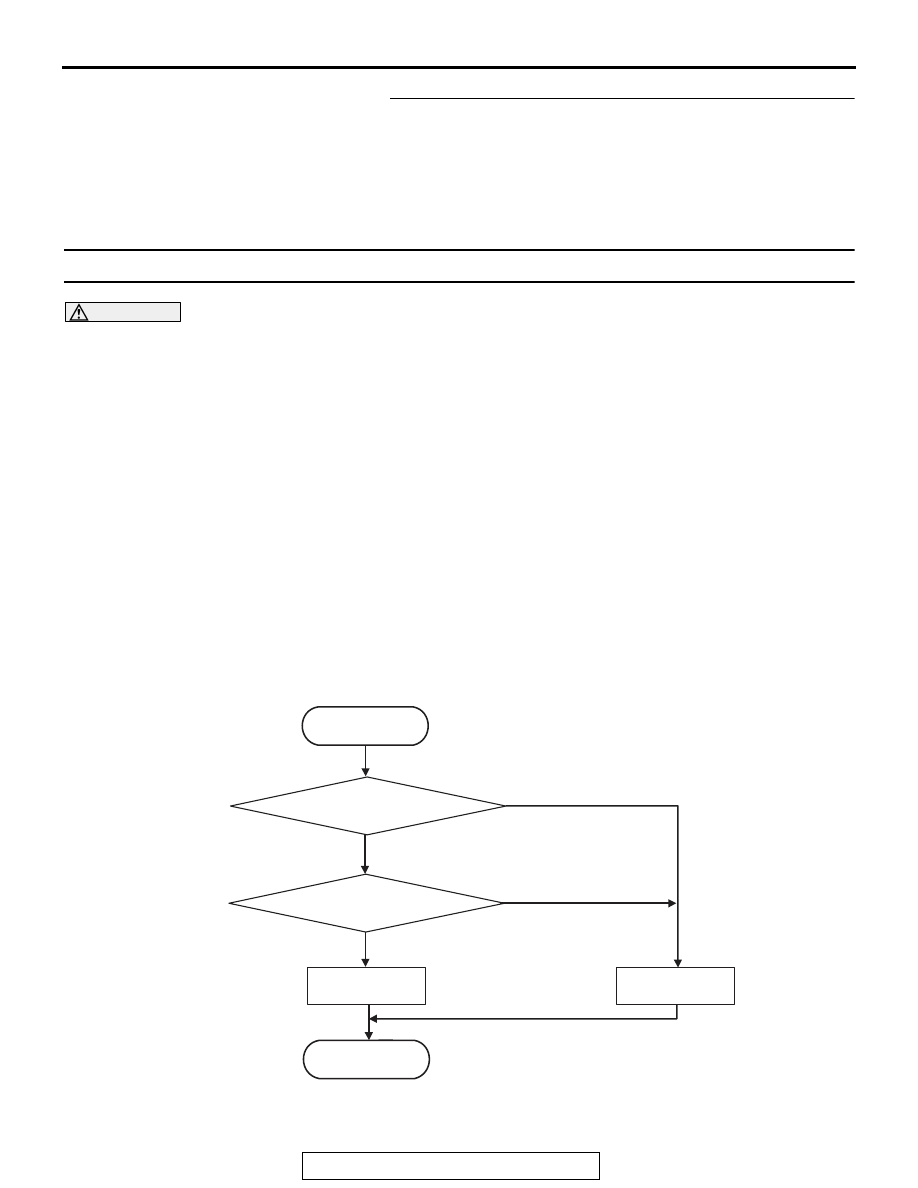
LOGIC FLOW CHARTS (Monitor Sequence)
.
AC710675
START
No
Good
Malfunction
END
Yes
Malfunction criteria met
Yes
Monitoring condition met
No