Mitsubishi Evolution X. Manual - part 366


  Index      Mitsubishi     Mitsubishi Evolution X - service repair manual 2008 year


Search            


Content   ..  364  365  366  367   ..


Mitsubishi Evolution X. Manual - part 366


DIAGNOSIS <S-AWC(SUPER ALL WHEEL CONTROL)>

TSB Revision

MANUAL TRANSAXLE

22A-113

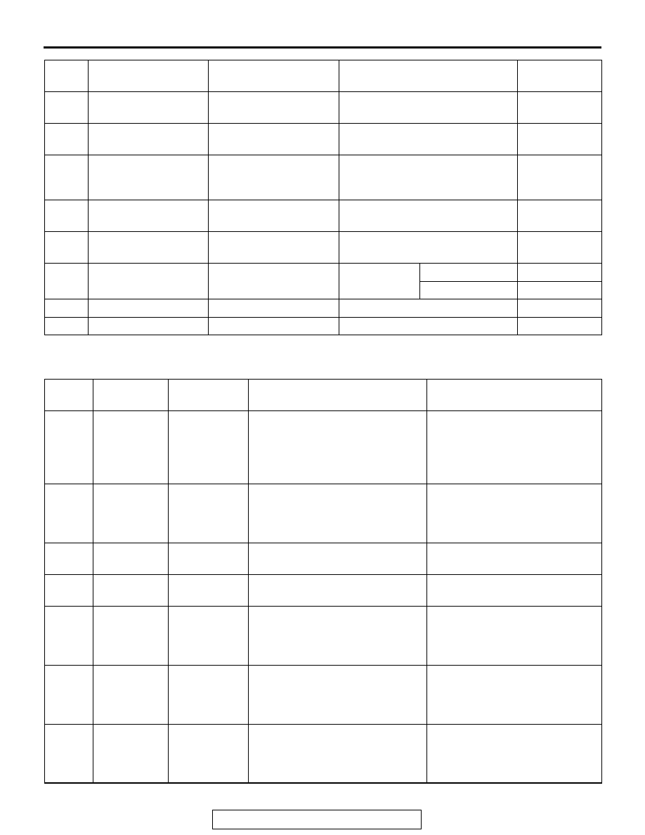
SPECIAL FUNCTION REFERENCE TABLE

M1221011300062

ACTUATOR TEST TABLE

97

Yaw rate sensor 
(adjusted value)

Yaw rate sensor 
(Correction amount)

Ignition switch: ON

−6 − 6 deg/s

98

SAS (adjusted value) Steering sensor 

(Correction amount)

Ignition switch: ON

−15 − 15 deg

99

Lateral G 
sensor(adjusted 
value)

Lateral G sensor 
(Correction amount)

Ignition switch: ON

−1.7 − 1.7 m/s

2

100

Longitudinal G 
(adjusted value)

Longitudinal G sensor 
(Correction amount)

Ignition switch: ON

−3 − 3 m/s

2

101

Chassis Number 
writing counter

Chassis number writing 
count

Ignition switch: ON

Writing count

102

Chassis Number 
(original) lock

Chassis number 
(original) lock

Ignition 
switch: ON

Locked

Lock

Unlocked

Unlock

103

Mileage counter

Mileage counter

Ignition switch: ON

Counter value

104

Coding counter

Coding count

Ignition switch: ON

Coding count

Item 
No.

Display on scan tool Item name

Check conditions

Normal 
conditions

Item 
No.

Display on 
scan tool

Check items Test content

Normal conditions

1

ACD air 
bleeding

Air bleeding 
<ACD>

According to the steering angle of 
steering wheel, energize the 
proportioning valve, and operate 
the proportioning valve for 5 
minutes.

No air comes out from the 
bleeder screw established to the 
transfer.

2

AYC air 
bleeding

Air bleeding 
<AYC>

According to the steering angle of 
steering wheel, energize the 
proportioning valve, and operate 
the direction valve for 5 minutes.

No air comes out from the 
bleeder screw established to the 
torque transfer differential.

3

Oil level 
check

Oil level 
check

Operate the direction valve to left 
and right for 20 seconds.

Oil level of reservoir tank is 
adequate.

4

Motor drive

Electric pump 
operation

Operate the electric pump for 3 
seconds.

Operating sound of the electric 
pump can be heard.

5

ACD 
operation 
check

ACD 
operation 
check

Operate the proportioning valve 
<ACD>, and supply the maximum 
hydraulic pressure to the 
multiplate clutch.

The tight corner braking 
phenomenon occurs.

6

AYC 
operation 
check (left)

Clutch 
operation 
check <left 
side>

Operate the direction valve, and 
supply the maximum hydraulic 
pressure to the left clutch.

With the wheels lifted, a speed 
difference is generated between 
left and right rear wheels.

7

AYC 
operation 
check (right)

Clutch 
operation 
check <right 
side>

Operate the direction valve, and 
supply the maximum hydraulic 
pressure to the right clutch.

With the wheels lifted, a speed 
difference is generated between 
left and right rear wheels.

DIAGNOSIS <S-AWC(SUPER ALL WHEEL CONTROL)>

TSB Revision

MANUAL TRANSAXLE

22A-114

1. The actuator test can be performed only when all 

the following conditions are satisfied.

• Every wheel speed sensor input is 20 km/h or 

less.

• No system malfunction is detected.

• The steering angle of steering wheel is within 

±30°  from the neutral position.

2. With the actuator test, when any of the conditions 

below is met, the forced activation will be 
canceled.

• Any of the wheel speed sensors detects an input 

of 20 km/h or more (excluding item No. 08 "Con-
trol OFF").

• A system malfunction is detected.

• The forced activation time has elapsed.

• Scan tool is removed.

• Scan tool clear key is operated.

SENSOR NEUTRAL POSITION LEARNED INI-
TIALIZATION LIST

Item No. Display on scan 

tool

Item

Initialization contents

1

SAS calibration

Steering angle correction 
amount initialization

Reset the steering angle sensor neutral position 
learned value.

2

Lateral G sensor 
calibration

Lateral acceleration 
correction amount 
initialization

Reset the lateral acceleration sensor neutral 
position learned value.

3

Longitudinal G 
SNS.calibration

Longitudinal acceleration 
correction amount 
initialization

Reset the longitudinal acceleration sensor neutral 
position learned value.

The sensor neutral position learned value initializa-
tion can be performed only when the vehicle is 
stopped.

AWD-ECU TERMINAL VOLTAGE REFERENCE CHART FOR ACD

M1221011400058

AC506684

22

9

16

15

2

14

1

3

19

6

18

17

4 5

20

7

21

8

25

12

23

10

24

11

26

13

JAE-E

39

50

44

4243

32

31

33

JAE-E

47

36

45 46

34 35

49

48

3738

52

51

40 41

C-46

AJ

8

Control OFF Control OFF

Turn OFF the electric pump relay, 
and turn OFF the ACD and AYC 
control.

With the actual driving of vehicle, 
there is a difference between 
when the control is ON and OFF.

Item 
No.

Display on 
scan tool

Check items Test content

Normal conditions

Ter
mina
l No.

Inspection Items

Inspection requirement

Normal Condition

1

Proportioning valve (for 
ACD)

With the actuator test 
(item No. 01), operate 
the proportioning valve 
<ACD>.

While executing the 
actuator test

0

−4 V

After completing the 
actuator test

1 V or less

DIAGNOSIS <S-AWC(SUPER ALL WHEEL CONTROL)>

TSB Revision

MANUAL TRANSAXLE

22A-115

2

Proportioning valve (for 
AYC)

With the actuator test 
(item No. 02), operate 
the proportioning valve 
<AYC>.

While executing the 
actuator test

0

−4 V

After completing the 
actuator test

1 V or less

3

Direction valve (right)

With the actuator test 
(item No. 07), operate 
the direction valve 
<right>.

While executing the 
actuator test

Battery voltage

After completing the 
actuator test

1 V or less

4

CAN-H

5

CAN-L

6

Pressure sensor power 
supply

Ignition switch: ON

Approx.5 V

7

Pressure sensor output 
voltage

Ignition switch: ON

0.5

−1.5 V

8

Pressure sensor 
ground

Any time

1 V or less

9

Local CAN (ASC-ECU) −

10

Local CAN (ASC-ECU) −

11

AWC switch power 
supply <Vehicles 
without steering wheel 
audio remote control 
switch>

Ignition switch: ON

Switch is operated to 
upper side (+) and held.

Approx. 1.6 V

Switch is operated to 
down side (

−) and held.

Approx. 0.3 V

Release the switch.

Approx. 4.7 V

12

Power supply

Any time

Battery voltage

13

Ground

Any time

1 V or less

14

Direction valve (left)

With the actuator test 
(item No. 06), operate 
the direction valve <left>.

While executing the 
actuator test

Battery voltage

After completing the 
actuator test

1 V or less

16

Ignition switch

Ignition switch: ON

Battery voltage

Ignition switch: OFF

1 V or less

17

Back up power supply

Any time

Battery voltage

19

AWC switch ground 
<Vehicles without 
steering wheel audio 
remote control switch>

Any time

1 V or less

20

Electric pump relay

When the electric pump motor is not operating

0 V

While the electric pump motor is operating

System voltage

21

AWC switch <Vehicles 
with steering wheel 
audio remote control 
switch>

Ignition switch: ON

Press and hold the 
switch.

Battery voltage

Release the switch.

1 V or less

Ter
mina
l No.

Inspection Items

Inspection requirement

Normal Condition

ON-VEHICLE SERVICE

TSB Revision

MANUAL TRANSAXLE

22A-116

ON-VEHICLE SERVICE

TRANSMISSION OIL LEVEL CHECK

M1221000900770

1. Remove the engine room under cover front B assembly. 

(Refer to GROUP 51, Under cover 

P.51-16

.)

AC707416AC

Center member

Centermember

Oil filler plug

Oil drain plug

2. Remove the oil filler plug and gasket.

AC700330AE

Gasket

Transmission oil

Filler plug hole

Oil filler plug

3. Check that the oil level is just below the lower edge of the oil 

filler plug hole.

4. Check that the oil is not excessively foul and has moderate 

viscosity.

5. Install the oil filler plug and new gasket, then tighten them to 

the specified torque.

Tightening torque: 32 

± 2 N⋅ m (24 ± 1 ft-lb)

6. Install the engine room under cover front B assembly. (Refer 

to GROUP 51, Under cover 

P.51-16

.)

TRANSMISSION OIL CHANGE

M1221001000800

1. Remove the engine room under cover front B assembly. 

(Refer to GROUP 51, Under cover 

P.51-16

.)

AC707416AC

Center member

Centermember

Oil filler plug

Oil drain plug

2. Remove the oil drain plug and gasket to drain the oil.
3. Install the oil drain plug and new gasket, then tighten them 

to the specified torque.

Tightening torque: 32 

± 2 N⋅ m (24 ± 2 ft-lb)

AC700330AE

Gasket

Transmission oil

Filler plug hole

Oil filler plug

4. Remove the oil filler plug and gasket, then fill the oil up to 

the lower edge of the oil filler plug.

Brand name: Mitsubishi genuine Dia-Queen New Multi 
Gear Oil SAE 75W-80 API GL-3
Quantity: 2.5 dm

3

 (2.6 quarts)

5. Install the oil filler plug and new gasket, then tighten them to 

the specified torque.

Tightening torque: 32 

± 2 N⋅ m (24 ± 1 ft-lb)

6. Install the engine room under cover front B assembly. (Refer 

to GROUP 51, Under cover 

P.51-16

.)


Content   ..  364  365  366  367   ..