Mitsubishi Evolution X. Manual - part 262


  Index      Mitsubishi     Mitsubishi Evolution X - service repair manual 2008 year


Search            


Content   ..  260  261  262  263   ..


Mitsubishi Evolution X. Manual - part 262


MULTIPORT FUEL INJECTION (MFI) DIAGNOSIS

TSB Revision

MULTIPORT FUEL INJECTION (MFI)

13A-25

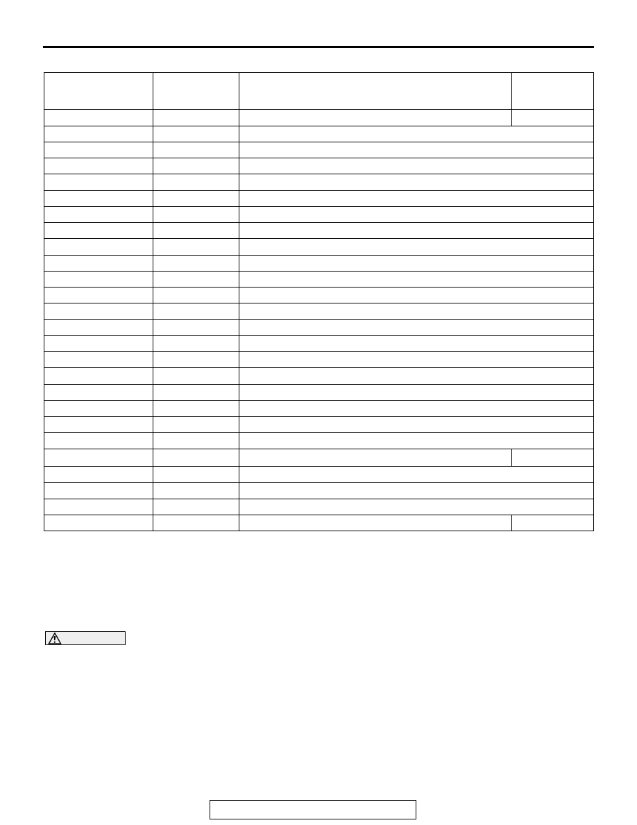
Freeze Frame Data for General Scan Tool

OBD- II DRIVE CYCLE

All kinds of diagnostic trouble codes (DTCs) can be monitored by carrying out a short drive according to the 
following 23 drive cycle patterns. In other words, doing such a drive regenerates any kind of trouble which 
involves illuminating the Malfunction Indicator Lamp (SERVICE ENGINE SOON or Check Engine Lamp) and 
verifies the repair procedure has been eliminated [the trouble the Malfunction Indicator Lamp (SERVICE 
ENGINE SOON or Check Engine Lamp) is no longer illuminated].

CAUTION

Two technicians should always be in the vehicle when carrying out a test.
NOTE: Check that the diagnosis trouble code (DTC) is not output before driving the OBD-II drive cycle. Erase 
the DTC if it has been output.
NOTE: Drive cycle patterns are not established for Vehicle speed signal monitor (DTC P0500), Power steer-
ing pressure switch monitor (P0551), and Fuel level sensor monitor (DTC P0461, P2066). Please reference 
the M.U.T. data list to judge whether these monitor items are normal. 

COMMON EXAMPLE of 
GENERAL SCAN 
TOOL DISPLAY

PRAMETER 
IDENTIFICATION 
(PID)

DESCRIPTION

UNIT or STATE

DTCFRZF

02

DTC that caused required freeze frame data storage Pxxxx, Uxxxx

FUELSYS 1

03

See M.U.T.-III Item No. C0

LOAD_PCT

04

See M.U.T.-III Item No. C2

ECT

05

See M.U.T.-III Item No. C3

SHRTFT 1

06

See M.U.T.-III Item No. C4

LONGFT 1

07

See M.U.T.-III Item No. C6

MAP

0B

See M.U.T.-III Item No. CC

RPM

0C

See M.U.T.-III Item No. CD

VSS

0D

See M.U.T.-III Item No. CE

SPARKADV

0E

See M.U.T.-III Item No. CF

IAT

0F

See M.U.T.-III Item No. D0

MAF

10

See M.U.T.-III Item No. AA

TP

11

See M.U.T.-III Item No. AB

RUNTM

1F

See M.U.T.-III Item No. D1

EVAP_PCT

2E

See M.U.T.-III Item No. D6

FLI

2F

See M.U.T.-III Item No. D7

BARO

33

See M.U.T.-III Item No. BB

VPWR

42

See M.U.T.-III Item No. D8

LOAD_ABS

43

See M.U.T.-III Item No. D9

EQ_RAT

44

See M.U.T.-III Item No. DA

TP_R

45

See M.U.T.-III Item No. BC

AAT

46

Ambient air temperature

° C (° F)

TP_B

47

See M.U.T.-III Item No. BD

APP_D

49

See M.U.T.-III Item No. BE

APP_E

4A

See M.U.T.-III Item No. BF

TAC_PCT

4C

Command Throttle Actuator Control

%

MULTIPORT FUEL INJECTION (MFI) DIAGNOSIS

TSB Revision

MULTIPORT FUEL INJECTION (MFI)

13A-26

DRIVE CYCLE PATTERN LIST

MONITOR ITEM

DIAGNOSTIC TROUBLE 
CODE (DTC)

PATTERN

Heated oxygen sensor (front) monitor <Readiness test 
item>

P0133

1

Heated oxygen sensor heater monitor <Readiness test 
item>

P0031, P0032, P0037, 
P0038

2

Catalytic converter monitor <Readiness test item>

P0420

3

Evaporative emission system leak monitor (small leak and 
gross leak) <Readiness test item>

P0442, P0455

4

Evaporative purge system monitor

P0441

Fuel tank pressure sensor monitor

P0450

Evaporative emission system leak monitor (very small leak) 
<Readiness test item>

P0456

5

Airflow sensor monitor

P0101

6

Manifold absolute pressure (MAP) sensor monitor

P0106, P0107

Intake air temperature sensor monitor

P0096, P0111

7

Engine coolant temperature sensor monitor

P0116, P0125

8

Thermostat monitor

P0128

9

Heated oxygen sensor (rear) monitor <Readiness test 
item>

P0139

10

Air fuel ratio feedback monitor

P0134

11

Heated oxygen sensor (rear) monitor

P0140

12

Fuel tank temperature sensor monitor

P0181

13

Misfire monitor

P0300, P0301, P0302, 
P0303, P0304

14

Fuel tank pressure sensor monitor

P0451

15

Power steering pressure switch monitor

P0554

16

Throttle position sensor plausibility monitor

P1233, P1234

Mass airflow sensor plausibility monitor

P1235, P1238

Torque monitor

P1241

Wastegate system monitor

P0234

17

Idle speed control system monitor

P0506, P0507

18

Idle speed control system monitor

P1506, P1507

19

Ignition timing retard control (cold start strategy) monitor

P1320

Variable valve timing system (MIVEC) monitor

P0011, P0014, P0016, P0017 20

Fuel trim monitor

P0171, P0172

21

Heated oxygen sensor monitor

P0131, P0137, P2195

22

MULTIPORT FUEL INJECTION (MFI) DIAGNOSIS

TSB Revision

MULTIPORT FUEL INJECTION (MFI)

13A-27

.

Intake air temperature sensor monitor

P0097, P0098, P0112, P0113 23

Airflow sensor monitor

P0102, P0103

Manifold absolute pressure (MAP) sensor monitor

P0108

Engine coolant temperature sensor monitor

P0117, P0118

Heated oxygen sensor monitor

P0132, P0138, P2252, 
P2253

Fuel tank temperature sensor monitor

P0182, P0183

Injector monitor

P0201, P0202, P0203, 
P0204

Turbocharger wastgate solenoid monitor

P0243, P0247

Knock sensor monitor

P0327, P0328

Crankshaft position sensor monitor

P0335

Evaporative emission purge solenoid monitor

P0443

Evaporative emission ventilation solenoid monitor

P0446

Fuel tank pressure sensor monitor

P0452, P0453

Fuel level sensor monitor

P0462, P0463

Engine oil control valve monitor

P1021, P1025

Engine RPM plausibility monitor

P1239

Barometric pressure sensor monitor

P2228, P2229

MONITOR ITEM

DIAGNOSTIC TROUBLE 
CODE (DTC)

PATTERN

MULTIPORT FUEL INJECTION (MFI) DIAGNOSIS

TSB Revision

MULTIPORT FUEL INJECTION (MFI)

13A-28

PATTERN 1

.

PATTERN 2

.

Drive cycle 
pattern

Inspection 
conditions

• Engine coolant temperature: More than 82° C (180° F)

• Barometric pressure: More than 76 kPa (22.5 inHg)

• Condition of TC-SST: Shift lever "D" range

Test 
procedure

1. Start the engine with all the accessories switched OFF.
2. Drive the vehicle for 4 minutes at the following conditions. (During the monitor)

NOTE: When the system is normal, the monitor is completed earlier.
• Vehicle speed: More than 30 km/h (19 mph)

• Engine speed: More than 1,500 r/min, less than 3,500 r/min

• Engine load: More than 20 %, less than 60 %

• Without rapid accelerator pedal movement

3. Stop the vehicle in a safe place and turn the ignition switch to "LOCK" (OFF) position.
4. Start the engine and do Steps 1 to 3 again.

NOTE: When the vehicle is operating normally and the OBD-II Drive Cycle is carried out, 
the Readiness Codes will be set as "Complete" on the first drive cycle. The second drive 
cycle is required to set the Readiness Codes as "Complete" if a fault is detected during 
the first drive cycle.

5. Confirm that the diagnostic trouble code (DTC) is not output.

AK402430

(2)

(1)

(3)

2 MINUTES

DURING THE MONITOR

1,500 - 3,500 r/min

IGNITION
SWITCH:
"LOCK" (OFF)

ENGINE SPEED

AJ

TIME

Test 
procedure

1. Start the engine with all the accessories switched OFF.
2. Let the engine idle for 10 seconds. (During the monitor)
3. Turn the ignition switch to the "LOCK" (OFF) position.
4. Start the engine and do Steps 1 to 3 again.

NOTE: When the vehicle is operating normally and the OBD-II Drive Cycle is carried out, 
the Readiness Codes will be set as "Complete" on the first drive cycle. The second drive 
cycle is required to set the Readiness Codes as "Complete" if a fault is detected during 
the first drive cycle.

5. Confirm that the diagnostic trouble code (DTC) is not output.


Content   ..  260  261  262  263   ..