Mitsubishi Evolution X. Manual - part 260
MULTIPORT FUEL INJECTION (MFI) DIAGNOSIS
TSB Revision
MULTIPORT FUEL INJECTION (MFI)
13A-17
CAUTION
To prevent damage to scan tool MB991958, always turn the
ignition switch to the "LOCK" (OFF) position before con-
necting or disconnecting scan tool MB991958.
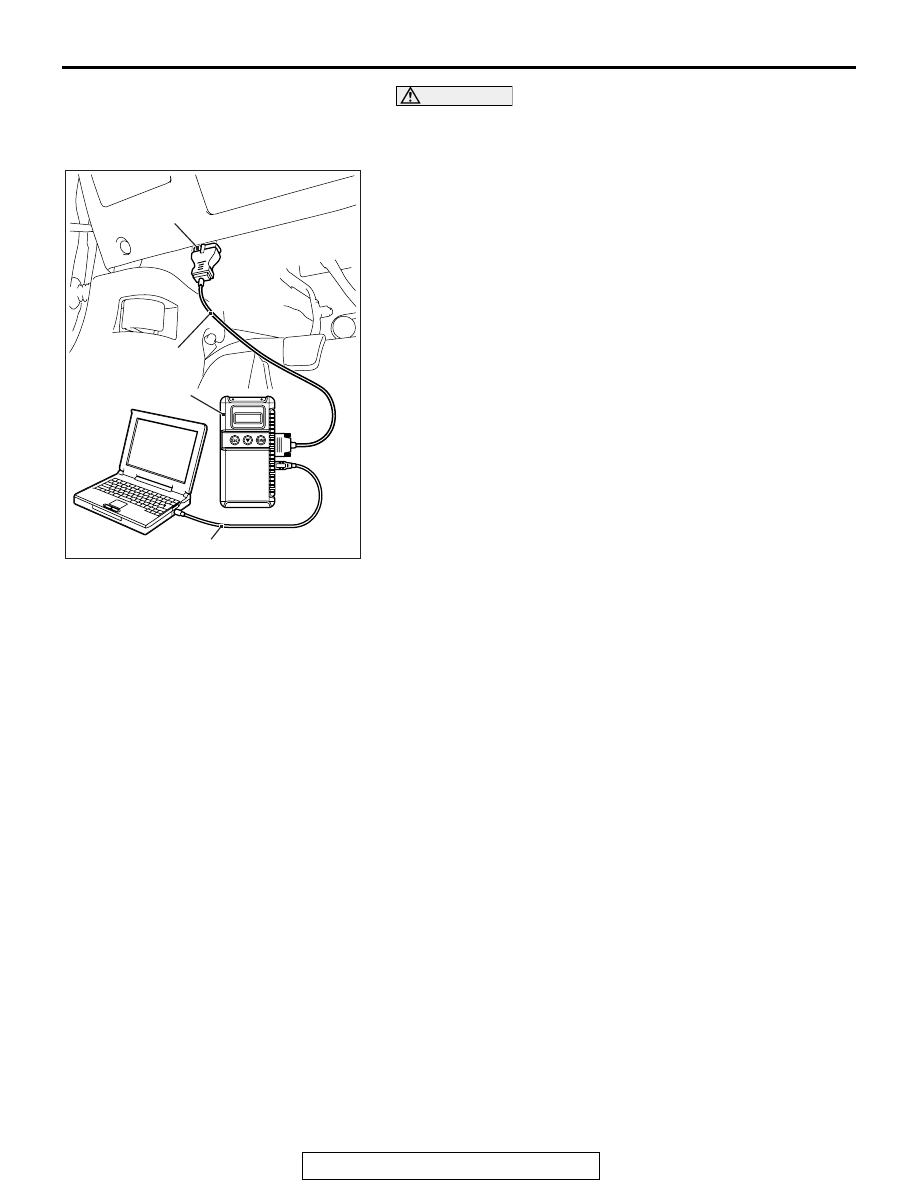
1. Connect scan tool MB991958 to the data link connector.
2. Turn the ignition switch to the "ON" position.
3. Select "System select."
4. Choose "from 2006 MY" under "MODEL YEAR".
5. Check that "Vehicle Information" contents are correct.
6. Choose "MFI".
7. Select "Actuator Test."
8. Choose an appropriate item and select the "OK" button.
HOW TO DIAGNOSE THE CAN BUS LINES
Required Special Tools:
• MB991958: Scan Tool (M.U.T.-III Sub Assembly)
• MB991824: V.C.I.
• MB991827: USB Cable
• MB991910: Main Harness A
AC608435
Data link connector
MB991827
MB991824
MB991910
AB